Dr. Raj Thiagarajan is a prolific producer of interesting research articles ranging from waste-water treatment to acoustics metamaterials, and lots in between. As the Managing Director at ATOA (“Atom TO Application”) Scientific Technologies, a COMSOL Certified Consultant, Raj has had to simulate all types of applications. Now he will show you how to use multiphysics simulations in multimaterial and composite product design.
Multiphysics Behavior of Multimaterial Composites
A multimaterial composite is a composite where either the matrix or the fibers, or the constituents, are composed of more than one material at macro-scale. An upcoming webinar will investigate the multiphysics behavior of these complex structures; thermal, acoustic, structural and electrostatic properties are all significantly affected when these more complex models are considered. Some can be treated on the macro-scale, while others need to consider the micro- and even nano-scale effects. Raj will show models on all these scales and the multimaterial design space for cost-effective and lightweight product design.
In one of Raj’s contributions to the COMSOL Conference, he presents how one can detect damage in composites through measuring electrical conductivity. In a carbon fiber reinforced polymer (CFRP), damage can be done on the micro-scale, through delamination and the breaking of the fibers themselves. It can also happen on the macro-scale, such as when a break occurs in the material itself, affecting both the fibers and the binding matrix together.
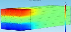
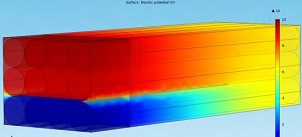
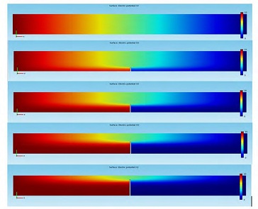
The damage is exemplified by the images below that show the measured electrical potential through varying stages of damage through delamination and fiber/matrix breakage. Micro-scale properties (the anisotropic electrical conductivity of the fibers) and macro-scale properties (the electrical conductivity of the matrix material) need to be coupled and simulated together.

|

|
Electric potential distribution of a whole and delaminated CFRP structure. The electrodes are placed at the top and bottom of the front portion of the multimaterial structure. Images copyright © ATOA Scientific Technologies.

Electric potential distribution due to the extent of the multimaterial (fiber/matrix) damage. Electrodes are placed to the left and right of the multimaterial structure. Images copyright © ATOA Scientific Technologies.
Webinar on Multiphysics, Multiscale, and Multimaterial
Some of the capabilities of ATOAST will be showcased on April 5th when Raj will be the guest speaker in our webinar on “Multiphysics and Multimaterial Design with COMSOL“. If you want to learn more about COMSOL’s capabilities in multiphysics, multiscale, and multimaterial applications, this webinar is for you.
Further Reading
- Multiscale Damage Detection in Conductive Composites
- Micro Mechanical Exploration of Composites for Superior Properties
- Effects of Fluid and Structural Forces on the Dynamic Performance of High Speed Rotating Impellers
- Property and Performance Prediction of Meta Composites for Novel Applications
- Multiphysics Simulations of Granular Sludge on the Optimization of Effluent Treatment Plant


Comments (2)
John Schmidt
March 27, 2013The problem that I have when trying to simulate the electrical conduction in CFRP using Comsol is that the differences in electrical conductivity is to great for Comsol to resolve. A normal carbon fiber has a conductivity of around 1e4S/m and a typically used polymer for this type of application has a conductivity of 1e-12S/m (doing the math, the difference in orders of magnitude is 16). This is because the machine precision of the code in Comsol is 2.2e-16, so the maximum difference in the order of magnitude of the conductivity should be smaller than sqrt(2.2e-16) = 1.49e-8. This means if the differences in order of magnitude of conductivity are over eight orders of magnitude, Comsol will give erroneous results. I have witnessed this many times. I am using the Electric Currents Interface within the AC/DC module.
I would like to know exactly how “the anisotropic electrical conductivity of the fibers … and the electrical conductivity of the matrix material” are coupled and simulated together.
Raj C Thiagarajan
April 3, 2013The CFRP used in our system has high volume fraction and we heave measured a longitudinal resistivity of 0.25 mOhmm and transverse resistivity 164 mm, and this range is not in insulator range. The conduction mechanism is governed by the conducting 3D network of carbon fibers. We used both micromechanical models with constituents and as well homogenized anisotropic conductivity models. So, your query/ problem is not related to the conductive network model of carbon fibres, shown above.
As you can see, this webinar is presented by ATOAST, we are COMSOL certified Industrial Design simulation consultants, and hence will be happy to study your problem and provide a commercial solution. Do contact us at ATOAST.HQ@atoastech.com
Do join us for the webinar for more.