Coupled Optical-CFD-CHT Analysis of a Pressurized Cavity- Air-Receiver for Concentrating Solar Power
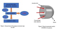
A solar thermal power plant comprises of an optical system, heat source and power block. Optical system collects direct sunlight and concentrates it onto the receiver (shown in figure 1). The receiver intercepts the concentrated sunlight and converts it to heat. Finally, the heat is converted to the thermal energy of the working fluid that drives the power cycle, thus generating electricity. However, currently the cost of electricity generation from concentrating solar power is much higher compared to conventional fossil fuels [1]. The reason being low efficiency of CSP plants which may be attributed to lower source temperatures. Currently, researchers are looking for efficient supercritical carbon dioxide (s-CO2) based closed loop Brayton cycle. As direct heating of s-CO2 is difficult owing to sharp variation in its thermophysical properties, indirect heating using pressurized air could be a possible option. This study deals with coupled optical, CFD and heat transfer analysis of a cavity air receiver (shown in figure 1) used for converting concentrated solar radiation to heat using pressurized air. COMSOL Multiphysics® was used to perform the coupled analysis. Two separate components were studied. One component had the 32 m2 Scheffler concentrator and the receiver cavity as the geometry. Under this component, the ray tracing analysis was carried out using the geometrical optics module. Receiver Cavity was positioned at the focal point of the concentrator whose surface was obtained analytically [2]. The 3D flux plot obtained from this study was used as heat flux boundary condition in the stationary study of second component. This coupling was made possible using general extrusion tool. Second component analysed the flow and heat transfer aspects of the receiver based on the flux result obtained from the first component. Initially, only pressurized air through the annular space was analysed and later, the annular space was modeled as a porous medium. The outlet temperatures in both the cases were compared for a range of flow rates. Cavity surface heat loss was modeled as reradiation loss, assuming a constant emissivity and natural convection loss calculated from Kraabel (1984) correlation [3]. Based on the results obtained from the coupled analysis, the receiver design is finalized and fabricated. For experimental validation of the numerical model, an experimental setup is created to test the receiver using pressurized air. 1. Kribus, A., Gray, Y., Grijnevich, M., Mittelman, G., Mey-Cloutier, S., & Caliot, C. (2014). The promise and challenge of solar volumetric absorbers. Solar Energy, 110, 463–481. 2. Munir, A., Hensel, O., & Scheffler, W. (2010). Design principle and calculations of a Scheffler fixed focus concentrator for medium temperature applications. Solar Energy, 84(8), 1490–1502. https://doi.org/10.1016/j.solener.2010.05.011. 3. Leibfried, U., Ortjohann, J. (1995). Convective heat loss from upward and downward-facing cavity solar receivers: Measurements and calculations.
Download
- sasidharan_presentation.pdf - 1.9MB
- sasidharan_paper.pdf - 0.21MB
- sasidharan_abstract.pdf - 0.03MB