Pipe Flow Module Updates
Nonisothermal Pipe Connection
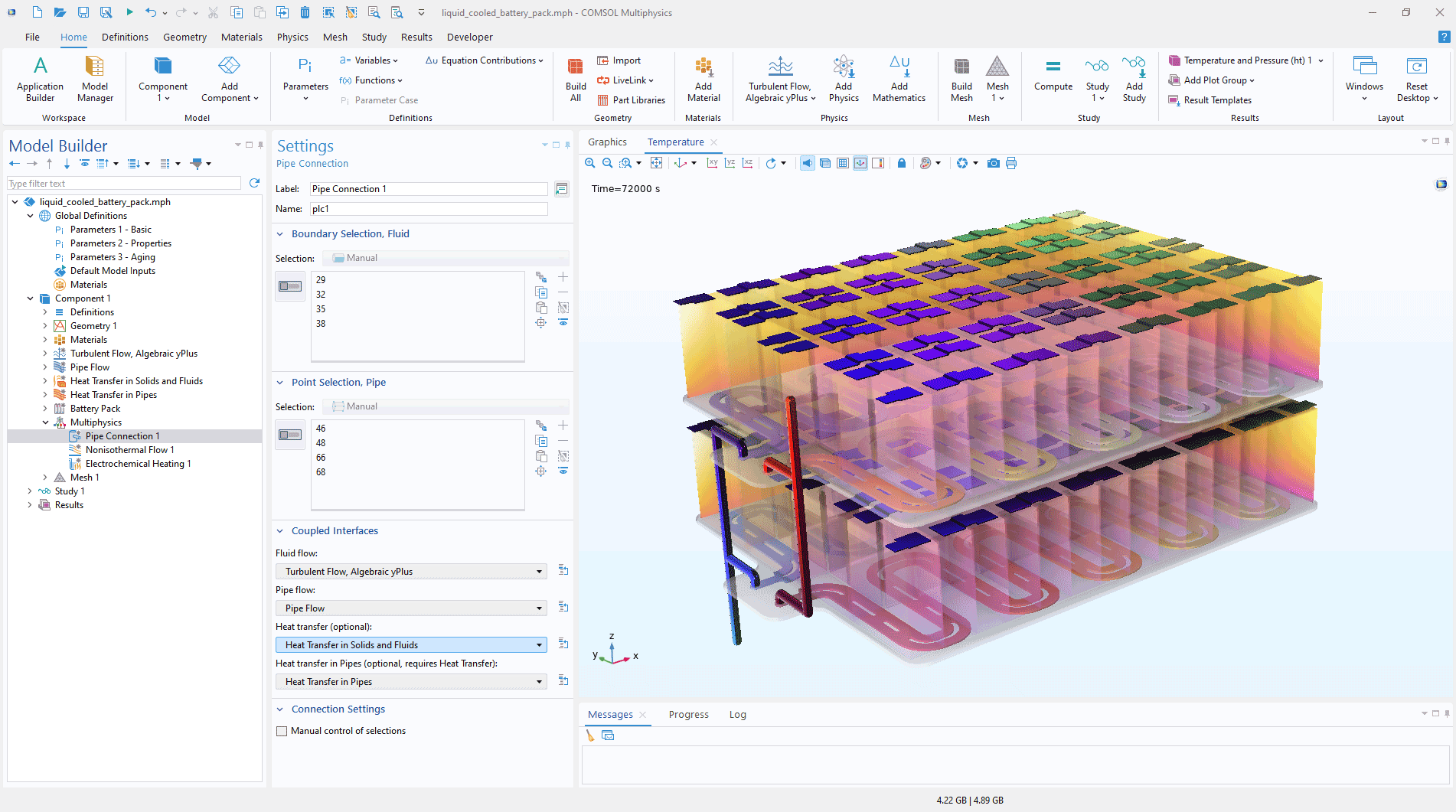
The Pipe Connection coupling feature now supports nonisothermal flow in addition to isothermal flow when both the Heat Transfer in Solids and Fluids interface and the Heat Transfer in Pipes interface are included in the model.. This feature automatically couples the pipe domain and the volume domains for both fluid flow and heat transfer, which otherwise would require manual setup of coupling operators. In addition, this update allows for temperature variations in pipe flow simulations without requiring the Heat Transfer Module — only the Pipe Flow Module is needed.

3D Visualization of Pipes
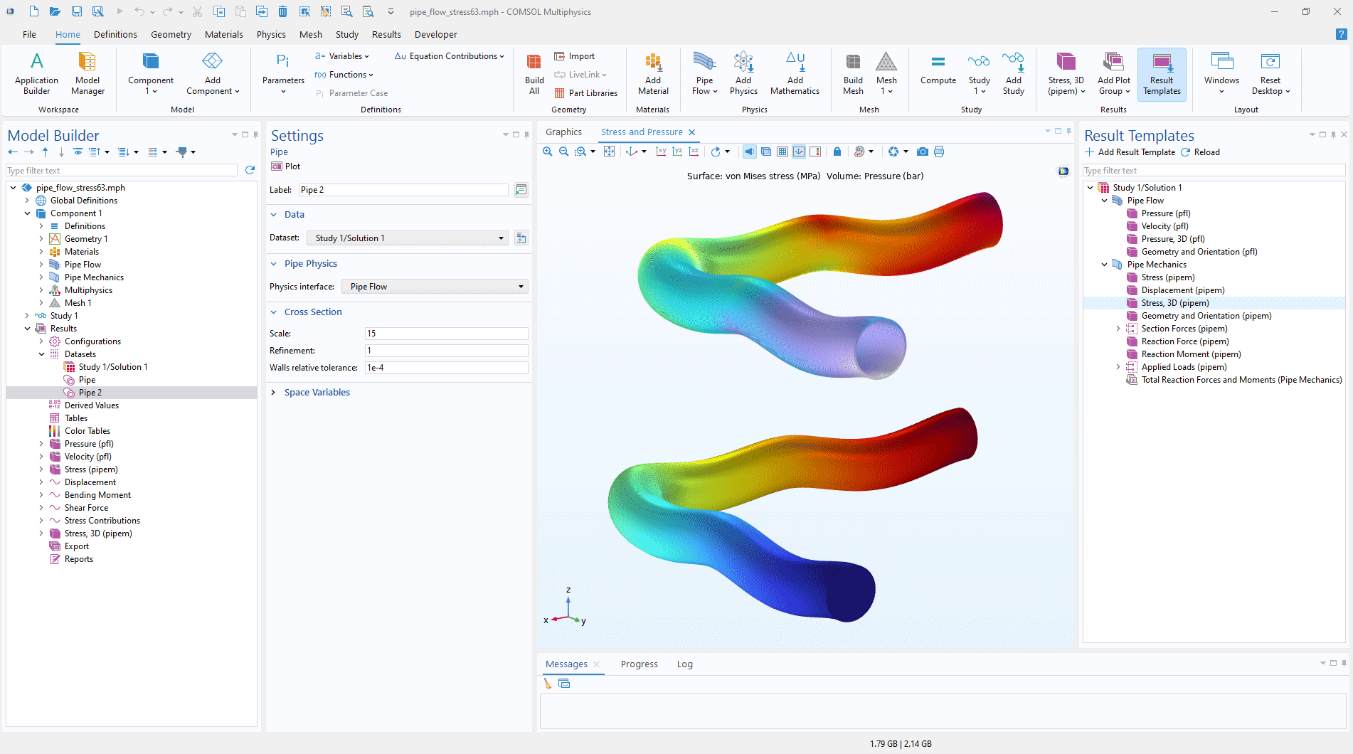
The pipe interfaces now support full 3D visualization, accurately representing pipe shapes and enabling detailed plotting of variables like stress and temperature variation across the pipe walls using the Pipe dataset. Several new plot types have been added to the results templates, allowing users to visualize geometry, stress, temperature, and pressure directly in 3D pipe models. The following tutorial models showcase the use of this new dataset:

