Designing Next-Generation Carbon Dioxide Removal Technology for Better Life in Space
NASA combines thermal modeling and experimental testing to find the best compressor design for the system that keeps the air breathable at the International Space Station.
By Fanny Griesmer
August 2024
The International Space Station (ISS) is made livable in great part thanks to a system that captures and removes carbon dioxide (CO2) from the air. The workhorse inside that system is a compressor, which fulfills its CO2-capture duties, but at a cost: it is both noisy and requires frequent maintenance. Engineers at NASA used modeling and simulation together with experimental testing to analyze the next generation of compressor designs that get the job done more quietly, with fewer maintenance needs, and at lower fabrication cost.
Contaminant Removal Technology Lets Astronauts Breathe on the ISS
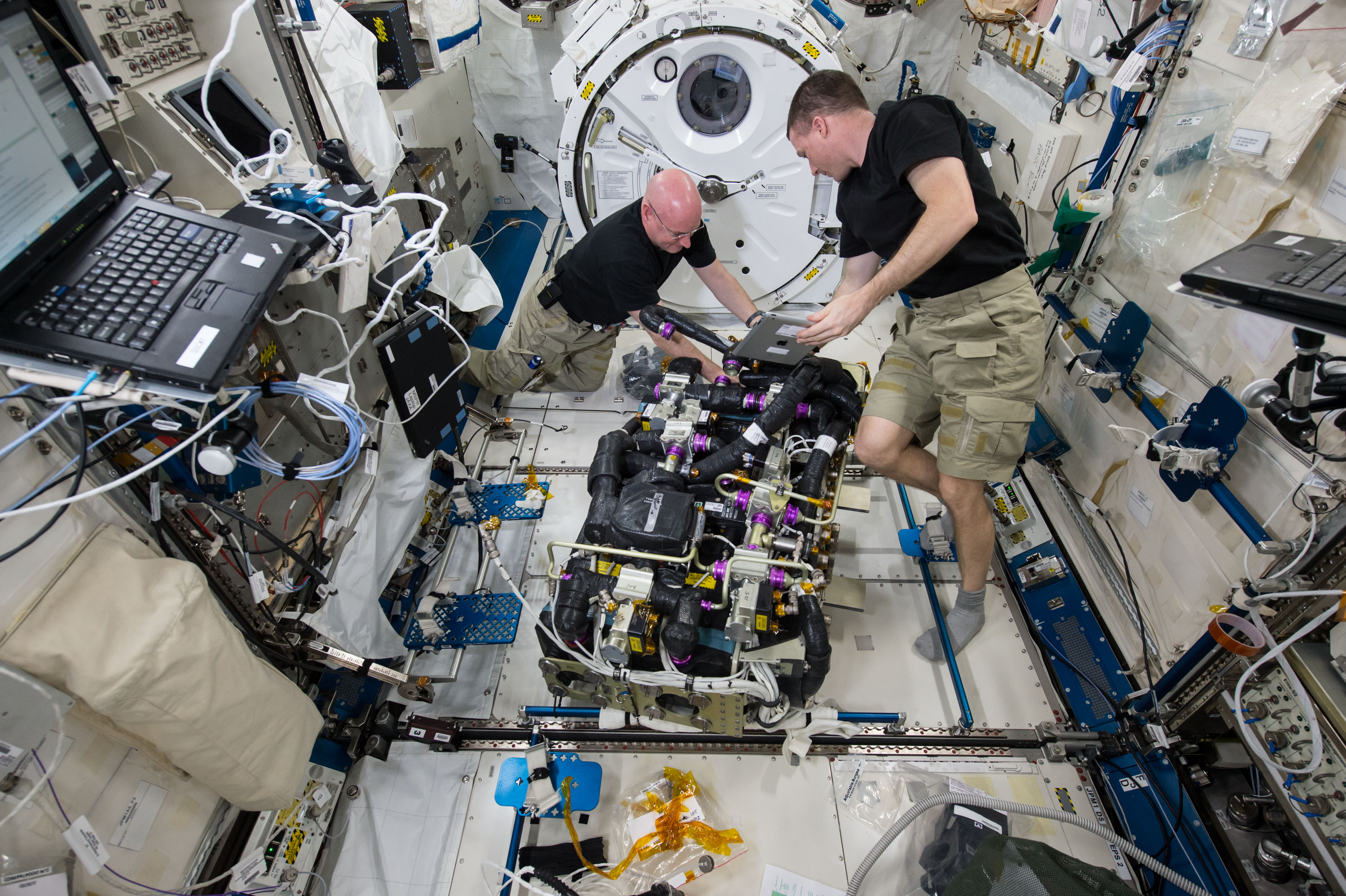
Astronauts signing up to live and work on the ISS put a lot of trust in the engineers behind the contaminant removal technology that rids the cabin of CO2 (Figure 1). "Currently, there is a system called the Carbon Dioxide Removal Assembly, or the CDRA," explained Dr. Hannah Alpert, an aerospace systems engineer at NASA Ames Research Center.
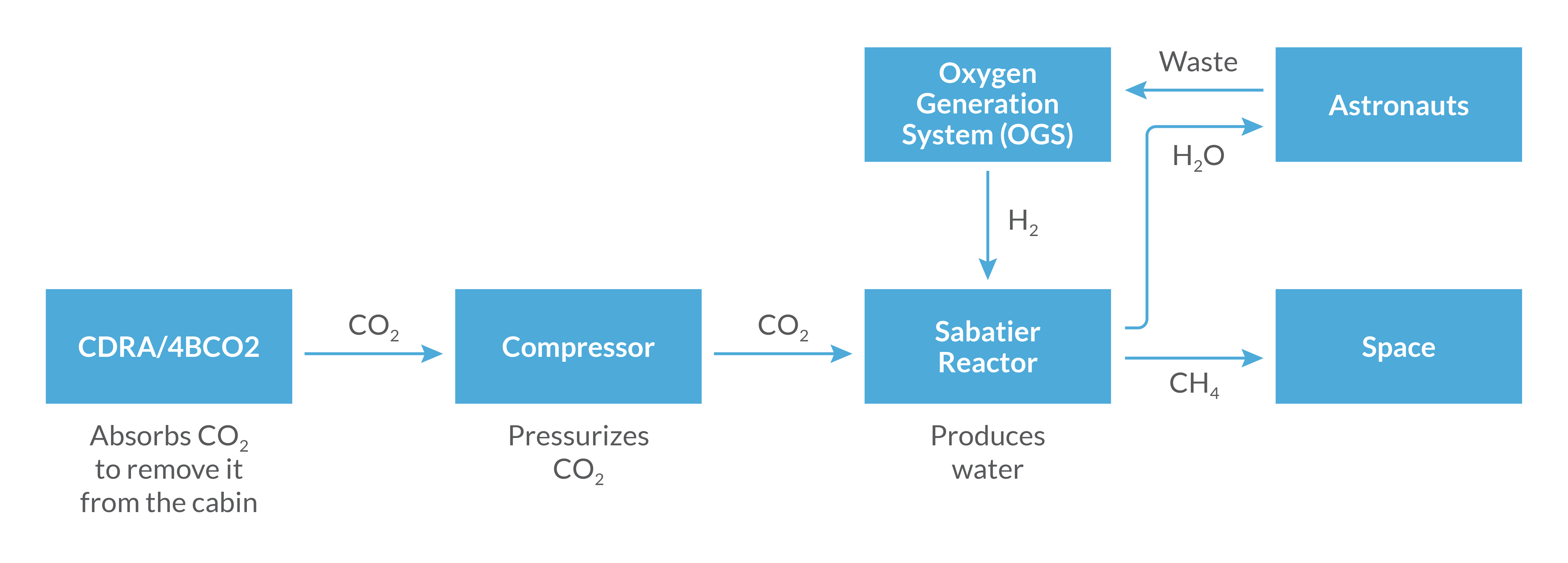
"The CDRA absorbs carbon dioxide to remove it from the cabin. Then that carbon dioxide is sent to a Sabatier reactor [where] it is combined with hydrogen from the oxygen generation system to produce water," she continued. That water is supplied to the astronauts for drinking. The system also yields methane, which is sent into space. (See Figure 2) "We have this closed-loop system to keep the astronauts alive, but in order for the carbon dioxide to work with the Sabatier reactor, it has to be at a higher pressure than what it is absorbed at, so we have a compressor in between the CDRA and the Sabatier reactor," said Dr. Alpert. The CDRA is currently being upgraded to a new four-bed molecular steam system: the four-bed, CO2 scrubber, or 4BCO2 in shorthand.
Dr. Alpert explained that the new system is meant to improve reliability and performance over the CDRA, which means that they are making various changes. For starters, the sorbent they were using for the CO2 capture has become obsolete, so that needs to be replaced. Additionally, they have redesigned some of the components. "They switched from a rectangular to cylindrical bed, redesigned the heater core to better distribute the sorbent and eliminate the void spaces, and they are adding a filter to capture dust and new valves for longer operating lifetimes," outlined Dr. Alpert. That said, the basic functionality as far as how the 4BCO2 integrates with the compressor that Dr. Alpert's team is working on is essentially the same as the current system.
Redesigning the Compressor
The current system features a mechanical compressor that is high mass and power, resulting in a lot of noise. The many mechanical rotating parts require frequent maintenance, and all in all it is expensive to both manufacture and run. "So we are looking at some alternative technologies and one of our leading options is called an air-cooled temperature swing adsorption compressor, or an AC-TSAC," said Dr. Alpert.
The new type of compressor is expected to bring many benefits to the ISS. "The AC-TSAC has lower mass and power requirements; it is much less noisy, so it is less annoying to the astronauts on the ISS; there are no rotating parts, so that will hopefully reduce the frequency of needing to replace parts; and then it is lower fabrication cost and easier to make," explained Dr. Alpert.
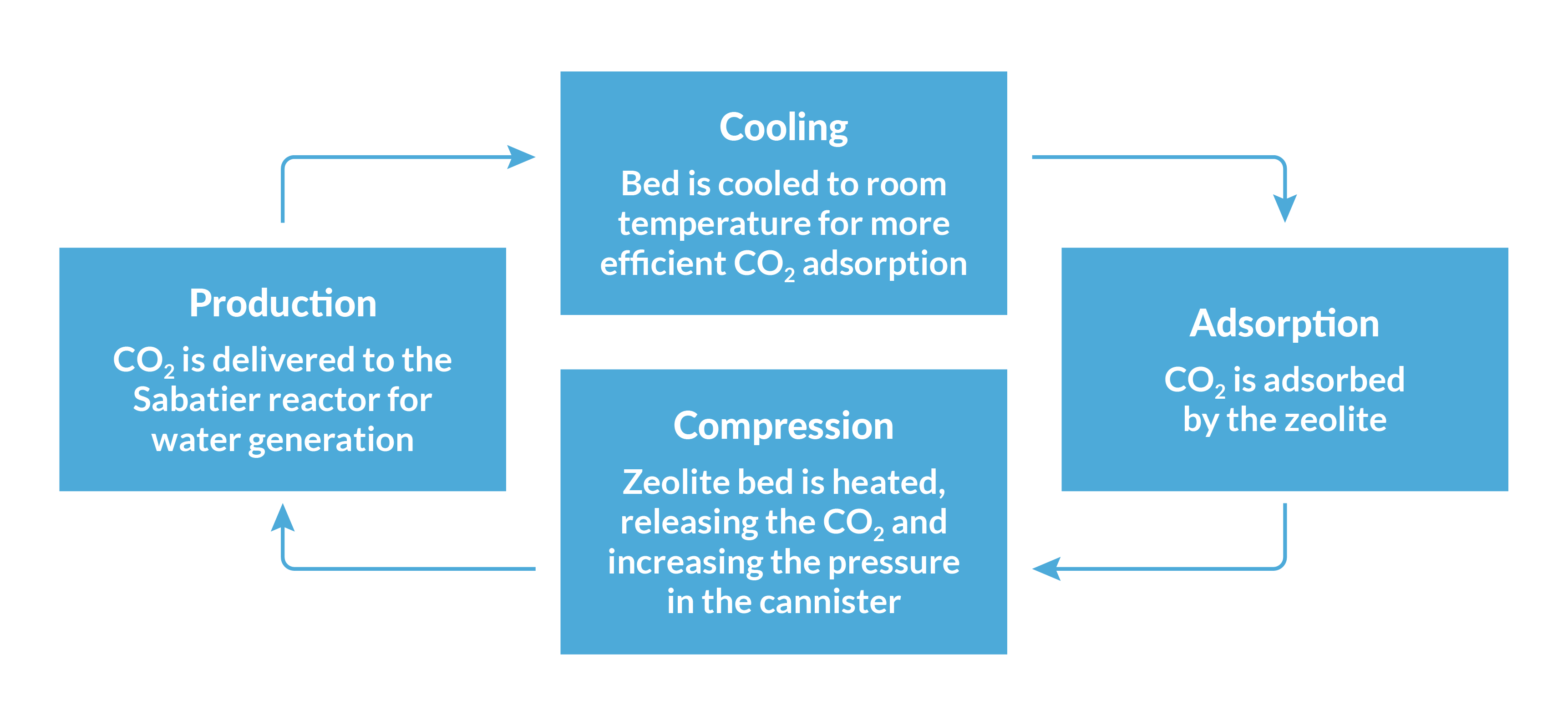
The AC-TSAC is a bed filled with minerals that capture CO2, called zeolite pellets, and it adsorbs CO2 more efficiently at room temperature. The full 150-minute cycle for pressurizing the CO2 is as follows: the AC-TSAC is cooled down to room temperature and adsorbs the CO2, then it is heated up to release the CO2 thereby increasing the pressure in the canisters. Next, the pressurized CO2 is delivered to the Sabatier reactor, which turns it into water. The cooldown period takes about 60 minutes, heating up takes another 25 minutes, and then it stays in the heating stage for about 75 minutes. To ensure that CO2 is constantly being supplied to the Sabatier reactor, the AC-TSAC is split into two beds, where one bed is in the heating and adsorption phase while the other is in the cooling and production stage, and then they switch (Figure 3).
The team has already developed one version of the AC-TSAC and now they are using thermal modeling to further improve on their designs.
Thermal Modeling Informs Next-Generation Design Choices
As she has done before in other projects, Dr. Alpert turned to the COMSOL Multiphysics® simulation platform to build models of the current AC-TSAC design. "We have found COMSOL® extremely useful over the past few years. One of the first projects I worked on when I joined NASA was modeling a heat flux gauge that flew on the Mars 2020 heat shield, and lately, I have been using the Optimization Module to reconstruct the surface heat flux on a heat shield, using the embedded thermocouple temperatures," Dr. Alpert said.
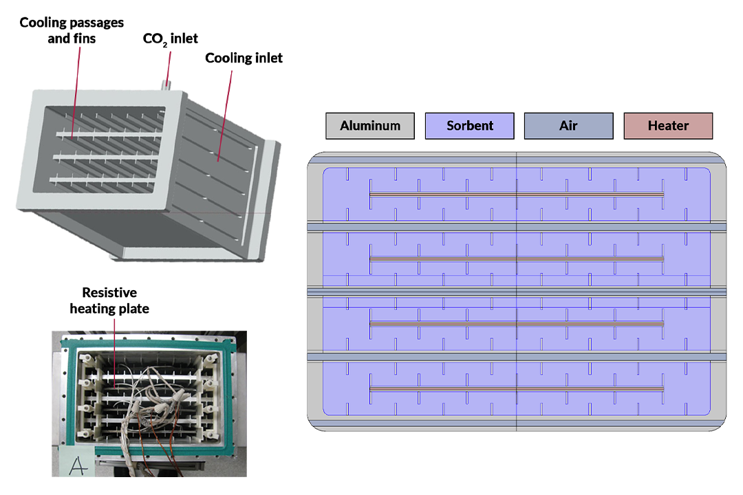
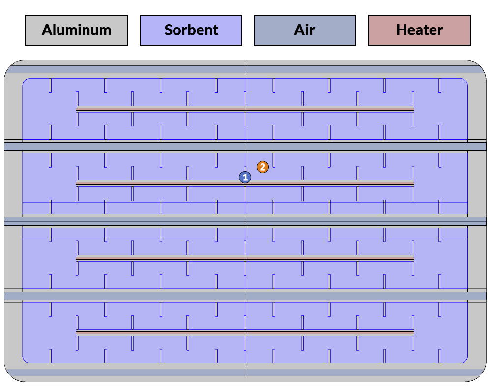
For the compressor project, she built both 3D and 2D versions of the model and after concluding that both produced the same results for her purposes, she moved forward with the 2D model, since it took less time to run. As represented in the model (Figure 4), inside the AC-TSAC there are three shelves in the middle and zeolite pellets packed into the open spaces. Between each of the shelves are resistive heating plates to heat up the bed. The cooling channels allow air to flow through during the cooling stage.
Validating the Model with Real-World Testing
To validate the model, the team used temperature and power readings from two test campaigns that were done on the AC-TSAC. As Dr. Alpert described, "The first one was a two-bed test for functionality at NASA Marshall in October of 2022. Then we did a more focused test campaign at NASA Ames, where we just used one bed to isolate the exact properties more."
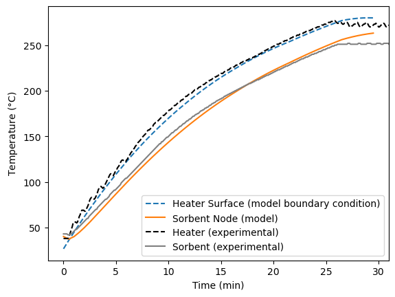
During the NASA Marshall test, they placed resistance temperature detectors in specific locations on the heater surface to measure the temperature. From there, they used the measured temperature as one of the boundary conditions of the model and ran the model to check if the modeled temperature matched the experimental data. The results matched very well, which gave Dr. Alpert and her team initial confidence in the model (Figure 5). Similarly, in terms of the power that was being input into the bed, the team was able to match the experimental data to the model. For this test, they only looked at the heating phase of the cycle.
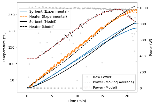
Next, to gain confidence in the power that was being applied, the team performed the focused test at NASA Ames, which tested just a single bed and collected experimental data from the heater surface and sorbent node. In this case, they used the measured power as input to their model and then they measured the temperatures at the heater node and sorbent node in the model. When they compared the model to the test results, they saw good overlap between the data (Figure 6).
Validated model in hand, Dr. Alpert and her team were ready to analyze how different design changes would affect the heating and heating rate of the compressor.
Design Trade Studies
As part of their search for the best new design, the team looked at four specific design trade studies: internal vs. external heaters, aluminum bed vs. vapor chambers, rectangle vs. cylinder bed, and total number of compartments. The overarching goal was to reach high temperature quickly and for the temperature to be uniform throughout the bed during ramp-up.
Internal vs. External Heaters
"The first design trade that we looked at was switching from internal heaters. Right now, there are internal heaters that are in the middle of the beds, and these internal resistive heaters are a potential point of failure. There are a lot of wires going into the bed and it is just a complex, messy, bundle of wires and heaters," said Dr. Alpert. This led the team to wonder if it would be possible to move those heaters to the outside the bed and if that would still heat up the sorbent quickly and uniformly. Using Dr. Alpert's model, they applied power to the internal and external heaters to compare the heating rate and uniformity (Figure 7).
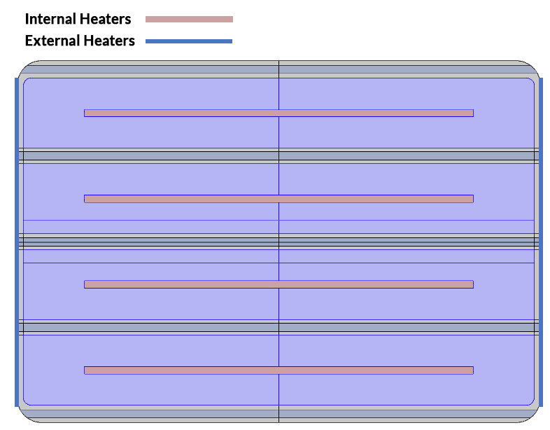
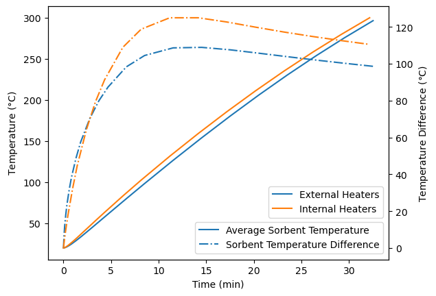
"What we saw here is that switching from internal to external heaters did not have a very big impact, which means that using external heaters rather than internal has the potential to improve or at least have the same amount of temperature uniformity of the sorbent while also reducing the complexity of the system," shared Dr. Alpert.
Aluminum Bed vs. Vapor Chambers
For the second design trade, the team wanted to study the effect of switching from an aluminum bed to using vapor chambers (Figure 8). As Dr. Alpert explained, "Vapor chambers are heat pipes that efficiently spread heat in multiple directions. Heat is applied at one end of a vapor chamber and then there is a small amount of liquid that is trapped in the chamber. That evaporates into vapor, which flows through the chamber, heats it up really fast, and then the vapor condenses once it reaches the cooler areas. Then through capillary action, the liquid flows back to the heat source and this cycle repeats." She continued, "This can give you an extremely high effective thermal conductivity on the order of 10,000 to 100,000 W/m-K."
NASA works with external partners that manufacture and test the vapor chambers and perform high-fidelity modeling, but for this analysis, the team modeled the vapor chambers using the material properties of aluminum, but at a much higher thermal conductivity, to get an idea of what the effects would be. Dr. Alpert noted that their main takeaway "is that when we switch to a vapor chamber bed instead of an aluminum bed, while the average sorbent temperature remains pretty much the same, using vapor chambers has the potential to improve the temperature uniformity of the sorbent." This was especially true in the cylindrical case, which is part of the third design trade study.
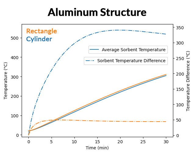
Rectangle vs. Cylinder Bed
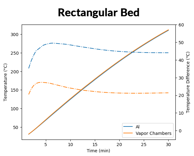
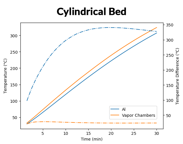
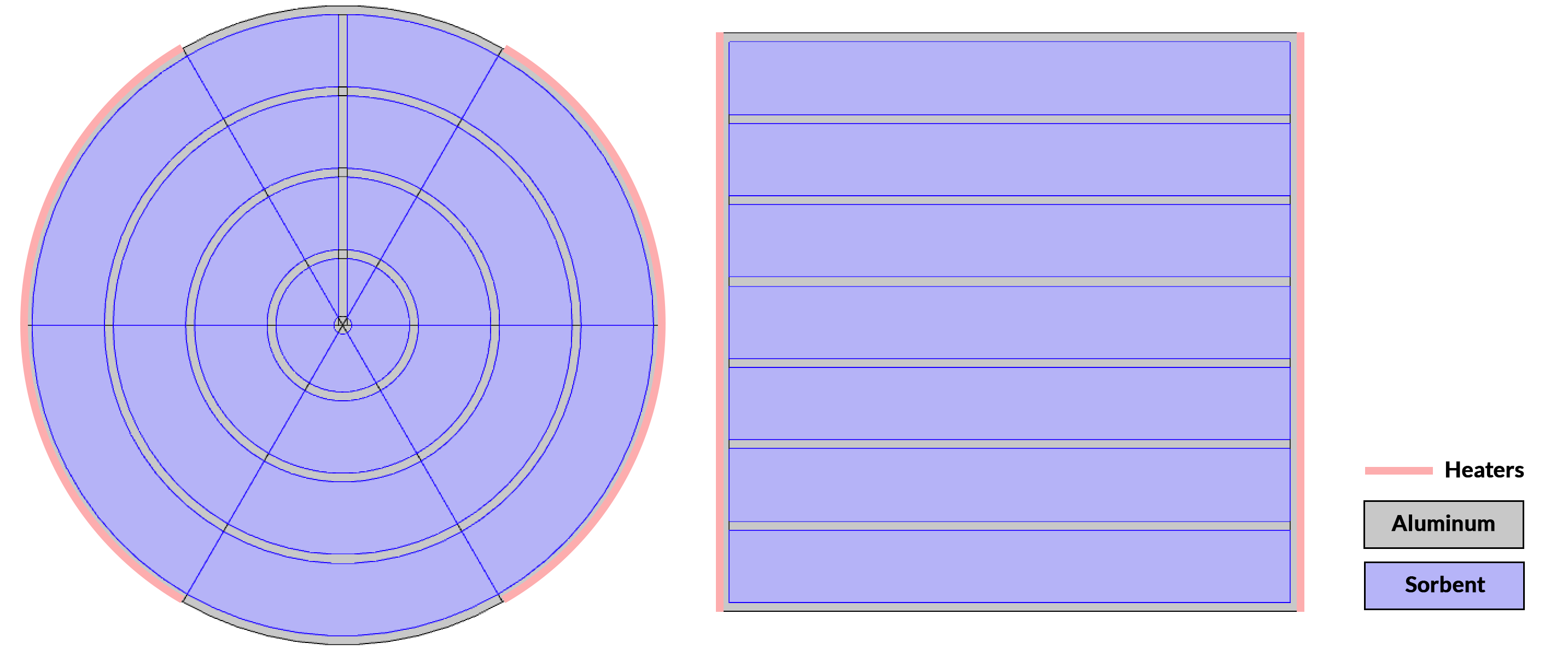
Dr. Alpert used a simplified model to get a sense of how changing the bed shape affects the temperature uniformity. "I kept the area of the sorbent the same. The distance between the aluminum or the vapor chamber is the same and the length of the heater is the same. So that is how I constrained the problem," she said. (Figure 9) The analysis showed that both shapes yield similar average sorbent temperatures, but the temperature uniformity is far worse in the cylindrical case when it is made of aluminum. This made sense to Dr. Alpert: "The sorbent is separated by aluminum walls and the heater is just on the outside. So the sorbent nearest the heater is going to get much hotter than the sorbent on the inside."
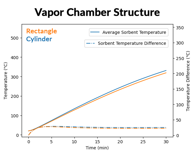
When they switched to a vapor chamber structure, the thermal conductivity is high enough that the heat very quickly flows through the walls. In that case, the team noted that the temperature uniformity is pretty similar between the rectangular and cylindrical bed shapes (Figure 10).
Number of Compartments
In the fourth design trade study, the team analyzed the number of sorbent compartments to see if adding more or having fewer compartments would affect the average temperature and the temperature uniformity (Figure 11). Dr. Alpert was not surprised to see that increasing the number of compartments improved the temperature uniformity, as that meant the chambers were closer together. "Each of the compartments is smaller, but we have added more thermal mass because there is now more aluminum in the system. So that decreases the overall heating rate for the average sorbent temperature," said Dr. Alpert.
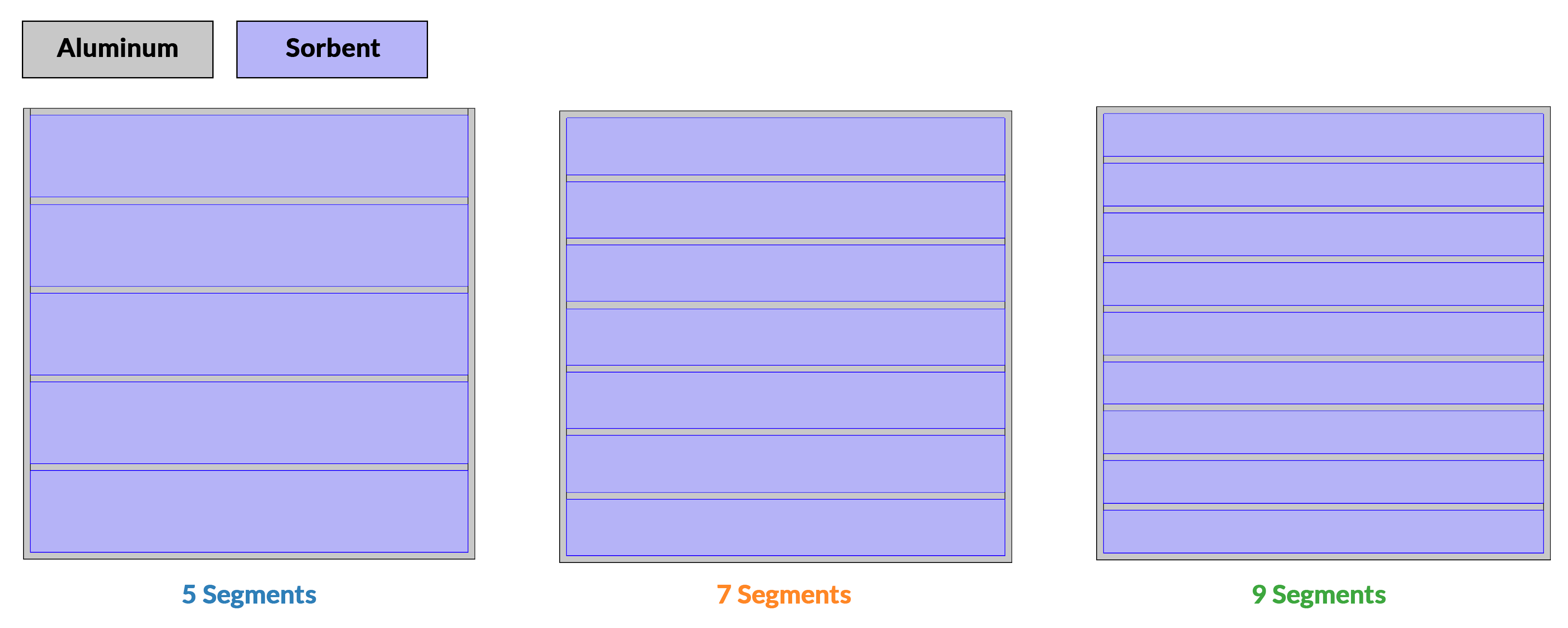
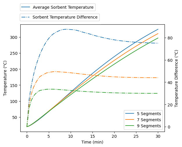
The team also found that keeping the same volume for the whole system, but adding more compartments, actually decreases the amount of sorbent that can fit within a given volume. In turn that would reduce the amount of CO2 that can be removed.
Performance Sensitivity Analyses
In addition to the design trade studies, the NASA team also sought to increase the thermal conductivity of the sorbent itself. "We wanted to see how much we need to increase the thermal conductivity and what the effect will be," specified Dr. Alpert.
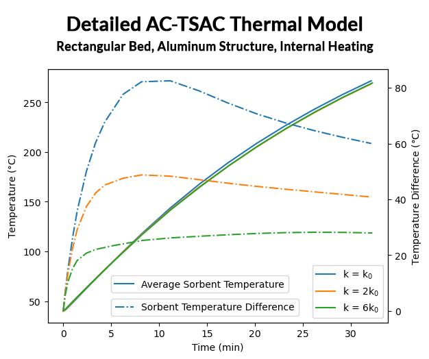
In the thermal model of the original AC-TSAC design, the team saw that increasing the thermal conductivity of the sorbent did not have much of an effect on the average sorbent temperature, but it did improve the temperature uniformity to a large degree. "That tells us that we are definitely going in the right direction and [as a result are] focusing a lot of our development efforts on that," said Dr. Alpert.
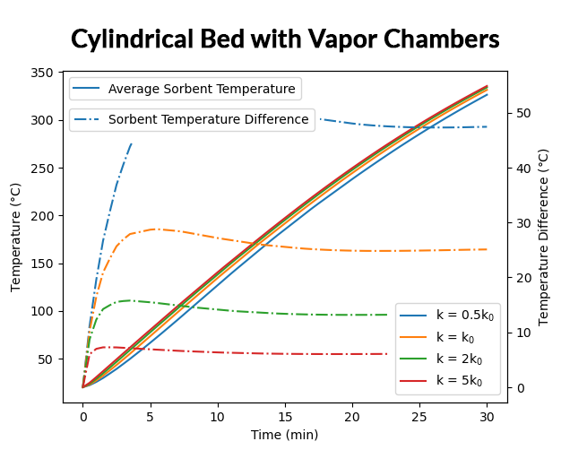
Similarly, when the team increased the thermal conductivity in their model of a cylindrical bed with vapor chamber, the simulation results showed a large improvement in the temperature uniformity of the sorbent throughout the bed (Figure 12).
Finally, the team analyzed the effect of increasing the input power. "Obviously, increasing the power would increase the temperature, but we wanted to get a sense for how much it would increase the heating rate and how much it would make the temperature less uniform," explained Dr. Alpert. The results showed that if they apply 1000 W instead of 600 W over 30 minutes, they can heat up an extra 100°C, but the temperature uniformity is reduced.
Combining Simulation with Experimental Testing to Find Better Designs
Dr. Alpert and her team successfully created a thermal model of the existing AC-TSAC and validated it against test data. Using the validated model, they were then able to determine what design parameters to change in order to get the desired results. Through simulation the team learned that external heaters reduce the system complexity and failure potential, vapor chambers have higher thermal conductivity and thereby improve the temperature uniformity of the sorbent, and they should continue to focus on increasing the sorbent thermal conductivity.
Looking ahead, Dr. Alpert noted that while they have so far only been examining the heating phase, they also need to look at the steady state and cooling phases of the cycle. The team will also continue to validate the thermal model with experimental data and account for mechanisms like heat loss.
"COMSOL is this nice multiphysics platform," said Dr. Alpert, "we can do more than just thermal here. At high temperature when the pressure goes up for the CO2, that has not yet been incorporated into the model. That is something we'll plan to do in the future."