Undocking Better Boat Landing Designs for Offshore Wind Turbines
Structural analysis helps an offshore engineering company design boat landings that withstand interactions with rough waters and 200-tonne vessels.
By Joseph Carew
September 2024
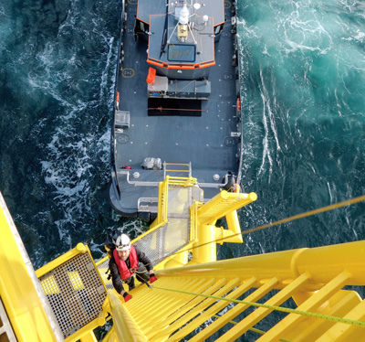
The sea churns, and a vessel is heaved back and forth as maintenance personnel approach an offshore wind turbine. The craft is pressed against the structure's specially designed boat landing, and the crew members begin to disembark. As they move from boat to turbine, a wave rolls the vessel away and then back toward crew members still on the lower section of the landing. Fortunately, disaster is averted as the steel fenders absorb the impact and the transfer proceeds safely.
Due to the relentless force of the sea, the vulnerability of personnel being transferred, and frequent interactions with weighty vessels, it is a given that boat landings have to be strong. Building up strength could involve adding steel, but without the right information to guide decisions, design engineers may end up adding material to pieces that do not actually need it, unnecessarily running up the final bill. Therefore, designing boat landings with an eye toward not only safety and strength but also an efficient use of materials is crucial to making offshore wind turbines operational.
To meet these challenges, Wood Thilsted, a leader in offshore engineering, developed a way to create, test, and validate boat landing designs cost effectively and efficiently — with both sea and safety in mind. Specifically, the team used the COMSOL Multiphysics® simulation software to reduce workload, minimize potential errors, and automate many of its design processes.
The Challenges of Docking
On a typical project, the team at Wood Thilsted will spend just one to two months designing a new boat landing that can withstand interactions with rough waters and 200-tonne vessels and last for 30 years. Louise Bendtsen, senior structural engineer at Wood Thilsted, said that when reduced to their most basic concept, these landings can seem misleadingly simple to create. Bendtsen recalled: "Someone once said: 'It is just tubes! It is not that difficult.' But it really is challenging." The demanding real-life requirements make offshore boat landings a daunting design prospect.
"The challenge with the design is that we have a set of requirements with different load cases, and these are contradicting. I can spend a lot of time optimizing one aspect of the design and then figure out that it does not work for another design case," said Bendtsen. "[As a designer, this means that you] need to have a broader perspective on the design as a whole and you cannot spend too much time focusing on one small detail, because it just will not work."
The need for maintenance personnel to safely transition from their vessel to the wind turbine using the boat landing adds to the complexity of its design. During this process, the bow of a specially designed, 200-tonne vessel is pressed against the fenders of the boat landing while the personnel transfer to the ladder on the structure and climb to safety. A boat landing needs to be able to withstand these impacts as well as the forces that waves will subject it to over the course of the projected 30-year lifespan. Engineers must also design for accident cases, such as unintended collisions, in addition to meeting the overarching load case requirements.
Finding the Ultimate Limit State and Fatigue Limit State
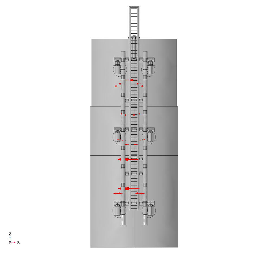
To best understand the capabilities of various designs, the team at Wood Thilsted needs a simulation software platform capable of modeling an ultimate limit state (ULS) wave as well as a fatigue limit state (FLS) wave, and, for this, it has turned to the COMSOL Multiphysics® software. The ULS wave represents the maximum peak forces that a boat landing is expected to experience throughout its projected lifespan, while the FLS wave stands for the cumulative impact of 30 years of waves and transfers on the structure. The ULS and FLS waves are the governing load cases for any potential design solution for safe offshore wind turbine access.
As boat landings include ladders, fenders, pins, and many other components, the Wood Thilsted team also needs to be able to test a variety of different designs to ensure user safety. However, altering each part individually and building the entire geometry again is time intensive. By using the COMSOL® software’s streamlined environment, the team quickly adjusts, tests, and optimizes key measurements, including the distance between rungs, the width of the ladder, the space between fenders, and the step-over distance.
Landing on a Design
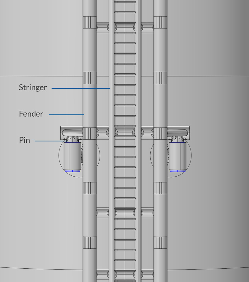
Wood Thilsted's designs for boat landings rely on steel and feature three sets of horizontal ladder supports that are welded to the transition piece of the wind turbine, where the turbine meets the water. The top support is a pin welded to a flange, which acts as the vertical restraint for the boat landing. The two lower supports are pins covered in vulcanized neoprene inside buckets. The neoprene ensures that there is no coating damage to the support system. Altogether, this design approach makes it possible to easily remove the boat landing in the unlikely event of a replacement being required before the end of its expected lifespan.
Automation with Simulation Software
In an effort to prevent having to perform repetitive analyses, an inefficient approach with regard to time and resources, the Wood Thilsted team has chosen to automate the simulations.
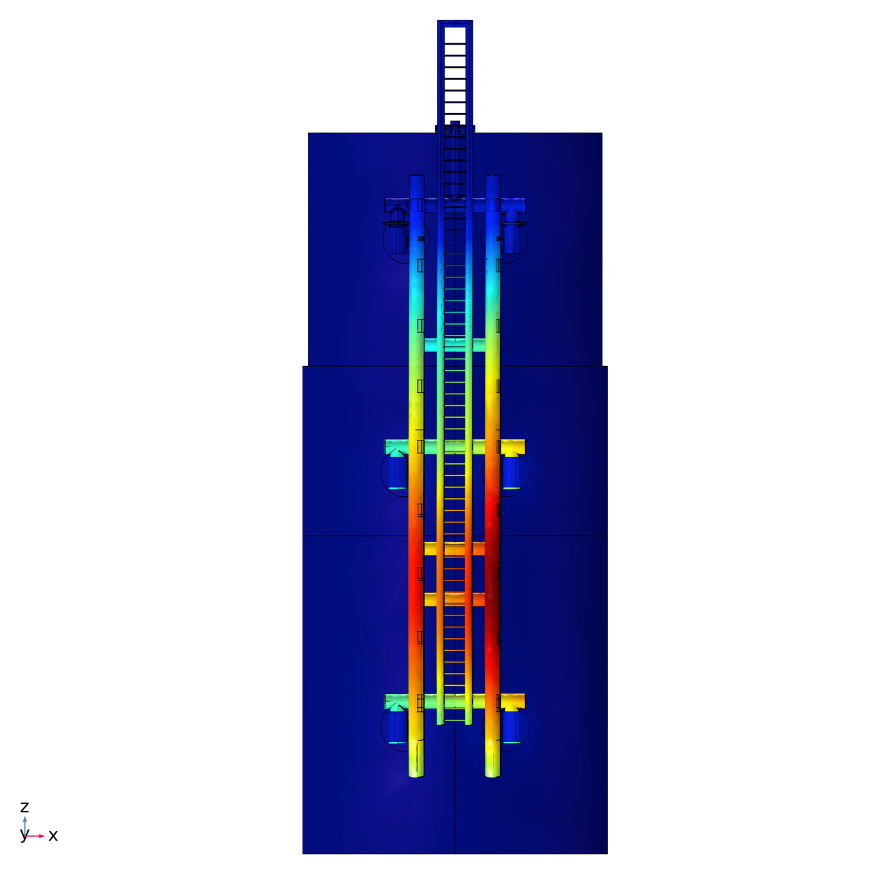
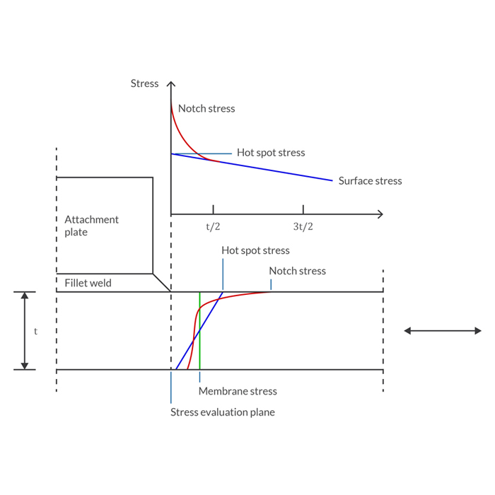
"We are using COMSOL to quickly and easily calculate what the stress concentration factors (SCFs) of our boat landings are and keep track of that throughout a project," said Bendtsen. To further validate potential designs, her team collaborates with Wood Thilsted's Primary Steel team for feedback on the SCFs and the limits of the materials being used.
The Wood Thilsted team uses LiveLink™ for MATLAB®, an add-on product to COMSOL Multiphysics®, to automate processes such as applying loads, setting material properties, and choosing the analysis type — thereby ensuring consistency and high quality.
"By using COMSOL Multiphysics®, we get the stresses automatically, and then we connect this data to MATLAB® using LiveLink™ for MATLAB®," said Bendtsen. "This allows us to write our own scripts that extract stresses and strains and perform all the results evaluations for the different load cases, freeing up time [for us] to improve the design and focus on [its] challenging parts."
These load cases include simulating normal wave loads as well as unexpected vessel impacts. All of this can be optimized and automated in COMSOL® by building up and storing information on particular parts. "There is a lot of opportunity for automation in the software, and that is really beneficial for us because we have all of these load cases that are similar but different," said Bendtsen.
Part Library and Parameters
Part of what allows Wood Thilsted to be efficient in its design approach is its geometry part library. Within COMSOL Multiphysics®, users can create designs and store them, as well as reproduce and parameterize their complex geometries. Using this functionality, Bendtsen and the team build their boat landing designs piece by piece, mapping out each part individually and saving its parameters so that they can swap out one design portion for another. This approach gives them the ability to alter multiple similar parts simultaneously by making changes to the corresponding governing global geometry parameter, allowing them to easily measure a design against previous iterations.
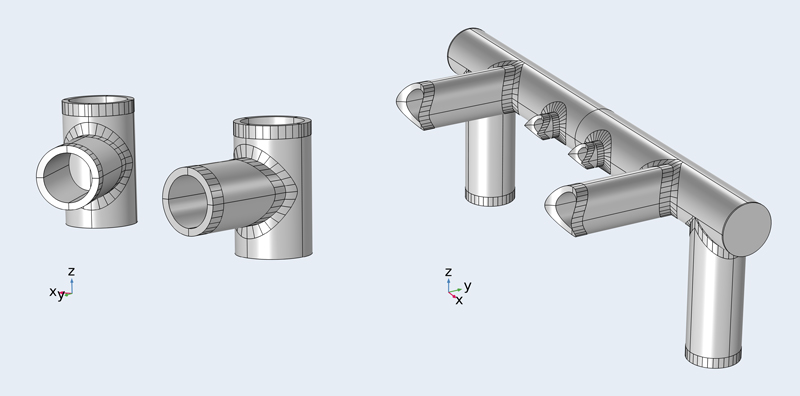
Specifically, Wood Thilsted has everything including the fender support, bucket support, fenders, and ladders in its geometry part library, and it is able to plug parts into a model as it needs. "That means I can combine these different geometry parts to build up my total boat landing design," said Bendtsen. "We also have multiple configurations in our parts, so I can change joint types and angles, making different configurations possible."
Bendtsen finds this particularly helpful when working with various fabricators after their designs have been modeled and simulated. Working with different fabricators leads to encounters with individualized preferences for actually building a boat landing. "We have a lot of different configurations, so we have created a part library that really allows us to configure our boat landing in many ways, and it is easy to adapt," said Bendtsen.
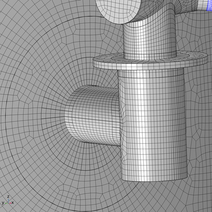
On top of that, Wood Thilsted's 3D COMSOL model allows the designer to easily perform a visual check of a potential design to verify that everything looks right. With structural mechanics simulation, the Wood Thilsted team is able to accurately model its boat landing designs and simulate the dramatic impact the environment and vessels can have on them.
Setting the Stage for Better Boat Landings
More than an assortment of tubes, boat landings need to be designed efficiently and with safety in mind. With so much at stake in terms of both costs and risks, modeling and simulation has helped remove guesswork from the process. Furthermore, Wood Thilsted has been able to automate parts of its processes and hone its wind turbine boat landing designs. "Clients continue to come to us to design boat landings because our designs have a track record and have been proven to work," said Bendtsen. This sentiment goes hand in hand with Wood Thilsted's motto to execute designs with speed and flexibility; as Bendtsen puts it: "Our project teams are agile and fast. We can handle design changes in hours instead of weeks, producing the most steel-efficient designs at fast speeds."
MATLAB is a registered trademark of The MathWorks, Inc.