When analyzing semiconductor devices, it is important to account for the multiple physics affecting their performance. The Semiconductor Module — an add-on product to the COMSOL Multiphysics® software — can help you model these complex devices. In this blog post, we discuss a new tutorial model of a 1D silicon solar cell, which is available with the latest release of the COMSOL® software, version 5.3.
The Far-Reaching Applications of Solar Cells
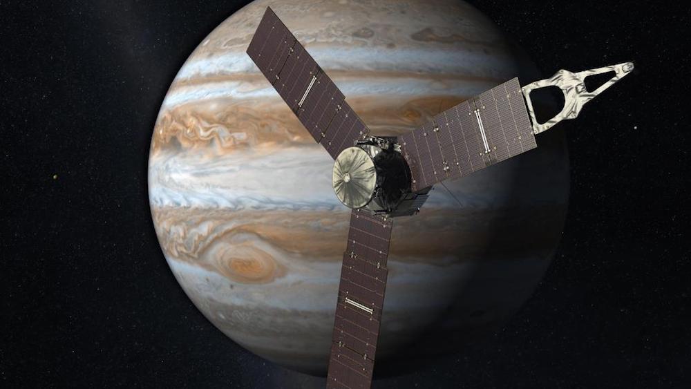
Solar, or photovoltaic, cells are used for applications such as recharging batteries in homes and even powering spacecrafts. For instance, NASA’s Juno spacecraft completed a mission to Jupiter partly thanks to the performance of its solar cells. The power generated by solar cells enabled Juno to gather new information about Jupiter, helping scientists to learn more about the planet.

Juno, NASA’s solar-powered spacecraft, near Jupiter.
For applications like the Juno mission to be possible, the solar cells involved need to be designed and analyzed accurately. In particular, engineers must pay special attention to the semiconductor materials. The semiconductor materials in solar cells absorb light, which is eventually converted into electricity. Thus, understanding how semiconductor materials, such as silicon (Si), function within these solar cells is essential to accurately analyzing their performance.
![]()
A solar panel that is comprised of silicon solar cells. Image by Lamiot — Own work. Licensed under CC BY-SA 3.0, via Wikimedia Commons.
The Semiconductor Module serves as a valid tool for analyzing these designs and accounting for all relevant physical effects. To better understand the functionality included in this add-on product, let’s explore the Si Solar Cell 1D tutorial, new with the release of COMSOL Multiphysics® version 5.3.
Modeling a Silicon Solar Cell with the Semiconductor Module
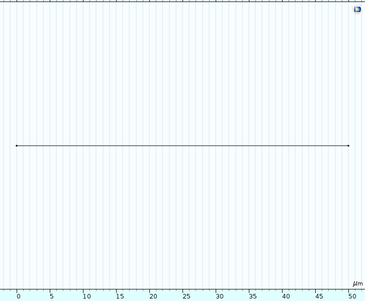
The solar cell model is comprised of a 1D Si p-n junction that includes a Shockley-Read-Hall recombination and carrier generation. Typically, the photo-generated carriers in a Si solar cell are swept to each side of a p-n junction’s depletion region. We can then extract electrical power by applying a small forward bias to the solar cell. The power is given by the product of the applied voltage and photocurrent. The goal of the model is to predict a Si solar cell’s behavior under this forward bias and with an applied voltage between 0 and 0.6 V.
Let’s take a look at the silicon p-n junction, which we form by p-doping the front surface of an n-type Si wafer. This n-type Si wafer is created by uniform bulk n-doping. Both forms of doping, front surface and uniform bulk, are easily accounted for by using a Geometric Doping Model feature and an Analytic Doping Model feature, respectively. We use a Boundary Selection for Doping Profile node to define the surface and add two Metal Contact features to specify the electrical connections between the front and back surfaces.

The 1D Si Solar Cell model.
We account for the main recombination effect with the Shockley-Read-Hall Recombination model, implemented via the Trap-Assisted Recombination feature. To simplify this model, we add an arbitrary user-defined expression to represent the generation rate with the User-Defined Generation feature. By doing so, we can avoid detailed modeling of the photovoltaic effect’s carrier generation mechanism.
It is also possible to add sophisticated expressions to make this model more advanced. For example, we can combine it with ray optics simulations to compute the Si solar cell’s performance for a certain date and location, as described in the Si Solar Cell with Ray Optics demo app.
Next, let’s discuss the results from the model.
Evaluating the Performance of a Si Solar Cell in COMSOL Multiphysics®
The first plot compares donor and acceptor concentrations for up to 10 μm beneath the solar cell’s front surface. As we see below, while donor concentrations remain the same, acceptor concentrations sharply decrease. To avoid accidental setup errors, it’s a good practice to check a model’s doping profile.
![]()
Comparison of the donor and acceptor concentrations.
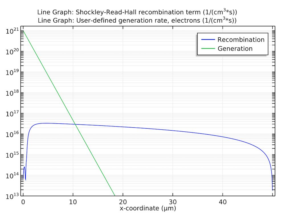
We can also investigate the Shockley-Read-Hall recombination rate and user-defined photo-generation rate for the entire cell’s thickness. The semilog plot below shows that, as expected, the user-defined expression for a single exponential function is a straight line.

Comparison of the Shockley-Read-Hall recombination rate and user-defined generation rate.
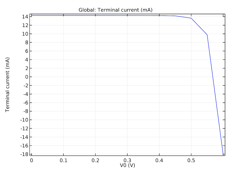
Finally, we plot the solar cell’s I-V and P-V curves. This enables us to visualize a few of the cell’s essential operating parameters, including the max power (~6.8 mW), short-circuit current (~14 mA), and open-circuit voltage (~0.57 V). Both the IV and PV curves generated by this model match those of typical solar cells, helping to verify the accuracy of the Semiconductor Module.
The solar cell’s I-V curve (left) and P-V curve (right).
The tutorial model we discussed here is only one example of how we can use the Semiconductor Module. Try it yourself with step-by-step instructions for setting up and running the simulation by clicking the button below.
Further Reading
- Check out additional updates to the Semiconductor Module on the Release Highlights page
- Read other blog posts about semiconductor modeling:


Comments (3)
Victor de Rezende Cunha
June 9, 2017Hi,
It’s quite interesting how you made this model, but I have a question. How was the light implemented?
Thanks.
Victor
Chien Liu
June 9, 2017 COMSOL EmployeeDear Victor,
In this elementary model, the light field is not explicitly simulated and the photo-generation is implemented as a simple math expression. In the more sophisticated app “Si Solar Cell with Ray Optics” (https://www.comsol.com/model/si-solar-cell-with-ray-optics-36201), the light is simulated using the Ray Optics Module and the resulting illuminance is fed into the semiconductor model.
Sincerely,
Chien
nick pv
February 10, 2018Hi,
For a long time, I’m looking for a 3D basic model of a conventional mc-Si solar cell or HIT cell with ray optic involved with front and back metalization and specified front passivation and pyramidic surface structure.
Just leave this comment here in case somebody will see it and have some templates.
In case that best and kindest comsol expert will see this comment I am leaving my email that you will be so kind to send me such model email: pvnick0@gmail.com
Appreciated.