When tracking the log for a time-dependent simulation, you can observe that the solver uses varying time steps and discretization orders. During the simulation, you might find that the time steps get smaller and the solution takes a long time to complete. Here, we will discuss the mechanisms used for selecting the time step and discretization order. In an upcoming blog post, we will explain which measures to take to improve the simulation efficiency in cases of small time steps.
Transient Simulations
Transient simulations need to compute a discrete solution that reflects the time evolution. Starting from initial values, the unknown transient degrees of freedom are determined by means of time-integration schemes. The computed solution from a time step gets accepted if the solution fulfills the predefined error bounds subject to the given tolerances. The adaptive time step algorithm can potentially use a time step that is too large, so that the error test does not pass for an already taken step. In these cases, the time step gets reduced and the step is repeated. The time step is also reduced if the nonlinear solver cannot solve the algebraic equations within the maximum number of iterations. Both these mechanisms involve extra work and can therefore lead to longer-than-optimal time-dependent simulations.
This blog post aims to help understand the mechanisms used behind the scenes and to help read and interpret the information provided in the solver log. In a follow-up to this blog post, we will use the understanding of these mechanisms to exemplify how we can make time-stepping more efficient and robust when small time steps are encountered. Let us first take a look at the solver log and see what we can understand from it.
The Time-Dependent Solver Log
A typical solver log of the time-dependent solver looks like this:
Step
|
Time
|
Stepsize
|
Res
|
Jac
|
Sol
|
Order
|
Tfail
|
NLfail
|
LinErr
|
LinRes
|
|---|---|---|---|---|---|---|---|---|---|---|
0
|
0
|
-out
|
2
|
3
|
2
|
0
|
8e-14
|
3.5e-15
|
||
1
|
0.1
|
0.1
|
11
|
5
|
11
|
1
|
0 |
1 |
2.6e-16 |
2.4e-16 |
... |
... |
... |
... |
... |
... |
... |
... |
... |
... |
... |
The log shows the iteration counter Step for the time integration loop at the current Time where Stepsize is the size of the current time step. The next three columns detail the total number of residual assembles (Res), the total number of Jacobian assembles (Jac), and the total number of linear algebraic system solutions ( Sol).
In this blog post, we are particularly interested in watching the discretization order of the time-stepping scheme (Order), the number of failures of the adaptive step-size selection (Tfail), and the total failures of the algebraic (nonlinear) solver (NLfail). We discuss the meaning of these failures in the following sections. Information about the solutions of the last linear problem for each time step is available in terms of the linear algebraic system error estimate (LinErr) and the size of the linear algebraic system residuals ( LinRes).
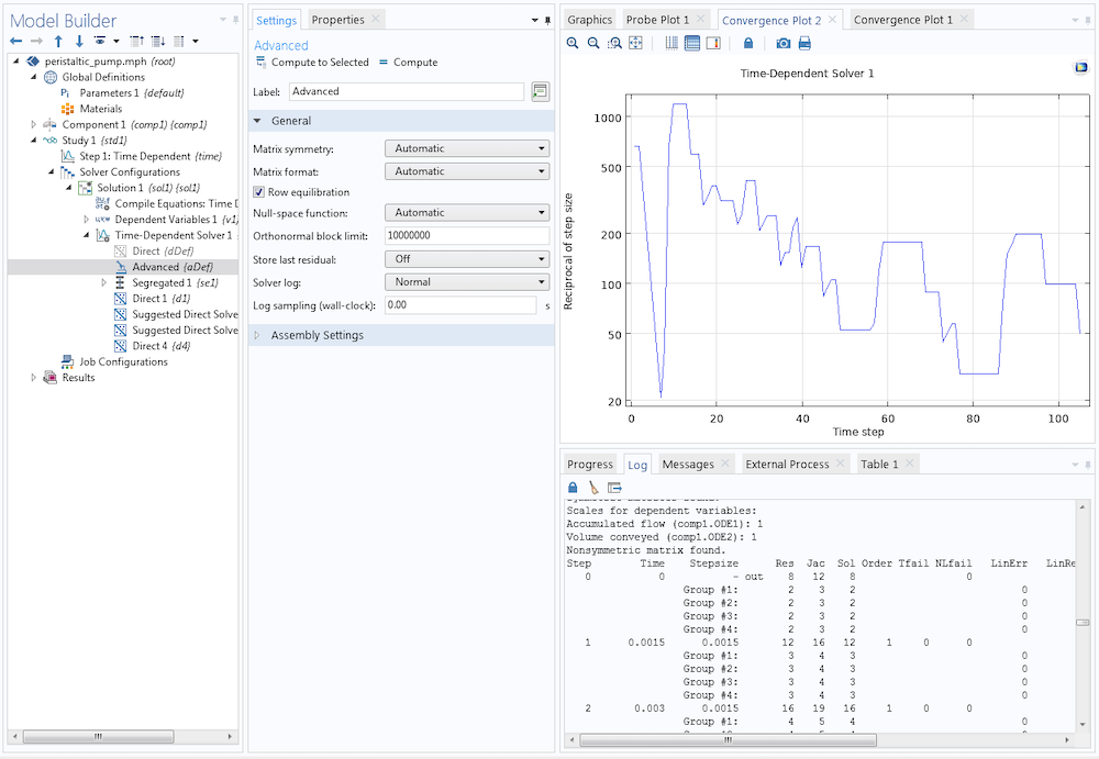
If you cannot find all of the time steps listed in the solver log, you can set the Log sampling (wall-clock) to 0 in the General section of the Advanced node for the Time-Dependent Solver. Sometimes it is helpful to add printouts from the individual algebraic solver iterations to the solver log by setting the Solver log to Detailed. The variation of the time step in the course of the simulation can be found illustrated in the corresponding Convergence Plot, where the Reciprocal of step size is printed for all time steps. Larger values in this plot indicate smaller time steps.
If you observe that the solver is taking very small time steps, it can be caused by several different reasons. One reason can be that your model is approaching some sort of singularity (physical or not), or that the solution is shooting off to infinity. Another reason can be that the model does not give a smooth time variation (for example, due to a too coarse mesh), which means that the error estimates will be difficult to fulfill for any time step. A third reason can be that the nonlinearities are difficult to handle (the algebraic solver does not converge). In order to see what the time step changes mean in detail, we have to dive deeper into the determination of the time step. Let us take a look at some time-stepping schemes used by the COMSOL® software.
Discrete Time-Stepping Schemes
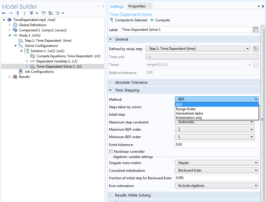
The Time-Dependent Solver in the COMSOL Multiphysics® software offers three different time-stepping methods: The implicit backward differentiation formula (BDF), Generalized alpha methods, and the explicit Runge–Kutta family of methods.
The BDF solver is an implicit solver that uses backward differentiation formulas with variable discretization order and automatic step-size selection. The higher-order schemes are used when the quality of the solution allows it, and the lower-order schemes are used when additional robustness is required. BDF methods are known for their stability and they are, by default, used for problems involving diffusion, convection, and reactions.
The Generalized alpha method is a second-order implicit scheme that is popular for structural mechanics problems, but it is also well suited for wave propagation problems. The Generalized alpha scheme allows us to control the damping for high frequencies and typically has less damping than the second-order BDF scheme. In many cases, it is more accurate than BDF but also less stable.
The Runge–Kutta family of methods are explicit methods that are typically used for systems of ordinary differential equations (ODEs). They are usually not as efficient for problems solved with the finite element method (FEM).
In this blog post, we focus on the BDF time-stepping scheme. The BDF scheme can be selected in the Time Stepping section of the Time-Dependent Solver. Depending on the physics of your model, it may already be selected.
Settings for Time Step Selection
In the Time Dependent study step, you provide the Times list by specifying an explicit list of times from the start time until the end time and intermediate steps. Using the range operator can be a quick way to specify a list of intermediate points of time. It is a common misconception that these intermediate points of time are the designated time steps taken by the solver, but these points are instead the output times where the solutions are stored for postprocessing and evaluation. The time steps taken by the solver are, by default, determined by an algorithm that tries to keep the errors (for each time step) within desired limits. The following settings are available for the Steps taken by solver in the Time Stepping section of the Time-Dependent Solver in order to affect the actual selection of the time steps:
- Free: An adaptive time step size is chosen based on the local error estimates. The time step is reduced or increased based on the current error estimates in relation to the tolerances. If the taken step still does not fulfill the error estimate, the step is redone with a reduced step (
Tfailis recorded in the solver log). This type of step-size reduction is therefore costly since the failed step is in vain. The time step is also reduced if the nonlinear solver loop does not converge within the maximum number of iterations (NLfailis recorded in the solver log). The specified output times are not related to the time steps taken by the solver. The solutions at the specified output times are computed by interpolation between steps taken by the solver. - Strict: The same as the Free setting, but the solver is adjusting its time step to solve also for the specified output times.
- Intermediate: The same as the Free setting, but the solver is adjusting its time step to solve also for at least one time in each of the subintervals defined by the output times.
- Manual: A user-specified time step is taken instead of an automatic one. The time step can be a constant, a global variable expression, or determined from the separation between a monotone list of time values. This time step is therefore fully user controlled, and the error test for the time step is disabled. Note, however, that the error estimates for the algebraic solver are still active, and therefore the tolerances are still important to consider. If the algebraic error estimate is not fulfilled after the maximum number of iterations, the time step is reduced.
In the following sections, we focus on Free time stepping. Intermediate and Strict time stepping can be used to combine the advantage of an adaptive time step selection with the manual enforcement of certain important modeling times or modeling time steps. Strict time stepping also avoids interpolation for the user-specified time list, which can be important for some applications. Note, however, that interpolation for the output can also be avoided with the Free method by selecting Times to store: Steps taken by solver.
Time Discretization
In COMSOL Multiphysics, a system of time-dependent partial differential equations (PDEs) is turned into an implicit system of ODEs (or differential-algebraic equations; i.e., DAEs) by means of a finite element spatial discretization. (Note that this is not the case for the discontinuous Galerkin method.) A time discretization (in the simplest case, a backward Euler scheme) is used to generate a set of algebraic equations for the unknown degrees of freedom. In every time step, the algebraic equations are solved by means of a Newton-like method (typically, a Fully Coupled solver or a Segregated solver with a damped Newton solver) using automatic linearization. The resulting linear equations are either solved by means of direct solvers (e.g., MUMPS or PARDISO) or by means of iterative solvers.
The implicit ODE system coming from the finite element discretization in COMSOL Multiphysics is solved with predefined accuracy requirements subject to the relative and absolute tolerances supplied by the user. There are two different types of requirements, one for the time-stepping (solver) error and one for the algebraic equation (solver) error. The first type is active for the Free, Intermediate, and Strict methods but not for the Manual method. The second requirement is always active.
It is a common misunderstanding to believe that the tolerances are not used when the Manual method is used. The time-stepping error requirement is based on an estimate of the local truncation error for the method used. The algebraic solver error is using very similar requirements, as when solving stationary problems, namely based on the size of the increment of the solution vector. But the normalization of this error estimate is adapted to the normalization used by the time-dependent solver. This is done to make the algebraic error norm comparable with the time-stepping error norm so that reducing the scalar factor for the algebraic solver error (Tolerance factor) should suppress the algebraic error evenly compared to the time-stepping error. It is sometimes important to reduce this factor to avoid polluting the computed solution with algebraic errors. In fact, if the algebraic error is not smaller than the time-stepping error, it can result in other problems, like time-stepping instabilities or failed error tests.
The two requirements mentioned, described further below, are central to solving an ODE system. But when this system stems from an FEM discretization, it is important to keep in mind that other sources of error are not taken into account. Examples are the truncation error for the FEM method, the quadrature error made by using numerical methods to approximate the finite element integrals, and the geometrical approximation error made by a polynomial representation of the actual geometry.
The Local and Global Truncation Errors and the Discretization Error
Let us take a closer look at the truncation errors. From the finite element discretization, we obtain an implicit ODE of the form
where U=[U_1(t), …, U_N(t)] is the vector of unknowns or the time-dependent degrees of freedoms and L is called the residual vector.
Here, we assume it contains only first-order time derivatives and we disregard constraint handling for simplicity. The BDF method of order q with variable step size \tau_k is defined by using the relationship
where the notation U^k is used as the approximation of the solution U(t_k) with step-dependent coefficients \alpha_{k,i} and \beta_k.
This representation illustrates the name backward differentiation formula. This formula can be used to eliminate the time derivative and to obtain an algebraic problem
The local truncation error at time t_k is defined as e_{k} := U^k – U(t_k;U^{k-1}), where U(t_k;U^{k-1}) is the exact solution fulfilling U(t_{k-1}) = U^{k-1}. By Taylor expansion of this solution, we obtain
and if we also Taylor expand the residual, we get
where the first term is identically zero per definition.
Under the condition that the mass matrix D = -\frac{\partial{L}}{\partial \dot{U}} is invertible, it follows that
for the scheme of order q.
For a noninvertible mass matrix, we have a DAE, and the error analysis is more elaborate, but the principles for adaptive time stepping are the same. Here, we have also assumed that the different time steps are somewhat related to each other so that the time steps do not change arbitrarily much from step to step. The global truncation error E^k := U^k-U(t_k) is what is important. This error gets contributions from all the local errors; conceptually, all the local errors add up. For a transient scheme of order q, and with constant time step \tau_k = \tau, we find (with a suitable normalization)
under suitable assumptions. Here, the constant C is strongly problem dependent. The local errors for an actual ODE problem can both be amplified or damped by the nature of the equation, so the notion of a simple sum of the local errors should be taken with a grain of salt. For the case of amplification of errors, for example, the constant can be very large. Furthermore, the local errors obtained with a constant time step can be vastly different during the simulation. These observations suggest that a good strategy for choosing the time step is to keep the local errors at the same level during the time stepping. It should also be possible to adjust the level for the local errors so that the global error can be controlled and, if necessary, reduced.
For a given discretization scheme, explicit expressions for the error estimate can be given in terms of
where C_k is a computable function of q and past step sizes \tau_j,\, j\le k.
For example, an explicit analog of BDF can be used to compute a predictor
An asymptotic analysis gives
with a computable constant \bar{C}_k.
Hence, we get a computable expression as an upper bound for the local truncation error in terms of
This computable expression is used in COMSOL Multiphysics as an approximation of the local truncation error, which in turn is used to control, or adapt, the time step.
Time Step Control for the BDF Time-Stepping Scheme
A time step in the BDF time-stepping scheme gets accepted if |\bar{e}_{k}| \le A + R |U^{k}| for an absolute tolerance, A, and a relative tolerance, R. In case of M fields with N_j degrees of freedom for field j, the time step gets accepted if the weighted root mean square norm of the error estimates
is less than 1. Here, \bar{e}_{k,i} is the estimate for the local truncation error for the scaled or unscaled field component U_i^k at time t_k and the scaled or unscaled absolute tolerance A_i. See the section “The Implicit Time-Dependent Solver Algorithms” in the COMSOL Multiphysics Reference Manual for details on the scaled and unscaled versions.
We find that the error per time step depends on two factors:
- The size of the time step, \tau_k
- The order q of the discretization scheme
Higher-order schemes give higher accuracy at higher costs, since the scheme involves more work to do. Shorter time steps give higher accuracy at higher costs because more time steps need to be computed in total. The adaptive BDF time-stepping scheme, adapting both the order and the time step size, tries to minimize the costs while maintaining the required accuracy. It makes sophisticated guesses for the time step and the order, but still, it can be that the result of the current time step does not obey the error limits. In this case, the time step will be repeated with a smaller time step \tau_k’ and a step failure Tfail is recorded.
Controlling the Impact of the Algebraic Error
Note that for nonlinear problems, a nonlinear system of equations needs to be solved for in every time step. This is typically done by Newton-like iterative methods that contribute with an additional algebraic error. Moreover, the linearized equations in the Newton method might be solved with iterative linear solvers that only approximate the exact solution of the linearized system to a certain degree.
The nonlinear solver might be failing to converge given a predefined number of iterations. In this case, the Jacobian matrix is updated and the time step is reduced, if necessary. In the log, you find that the counter NLfail is increased. The algebraic solver error is estimated by checking the increments \delta^{k,m} := U^{k,m}-U^{k,m-1} of the mth iteration in time step k, where U^{k,m} is the approximation to U^k in the Newton iteration m (see, for example, SUNDIALS: Suite of Nonlinear and Differential/Algebraic Equation Solvers).
The algebraic error |U^k-U^{k,m}| may pollute the truncation error and affect the stability. You need to ensure that the algebraic error is sufficiently small. The Tolerance factor (set in the Method and Termination section of the Fully Coupled and Segregated solvers) is a safety factor that can be used to suppress the algebraic error compared to the truncation error. The weighted norm used for the truncation error is, in similar form, also used for the algebraic error. Decreasing the Tolerance factor typically leads to an increasing (or the same) number of iterations in the nonlinear solver.
For an individual time step, it is more costly to solve the equations with a smaller Tolerance factor. Note, however, that using a Tolerance factor that is too large can lead to algebraic errors, disturbing the time-stepping method and leading to an incorrect time step selection, an inaccurate method, or an unstable method. The last two effects can also be the result for the Manual time-stepping method.
Time Step Selection and Order Selection
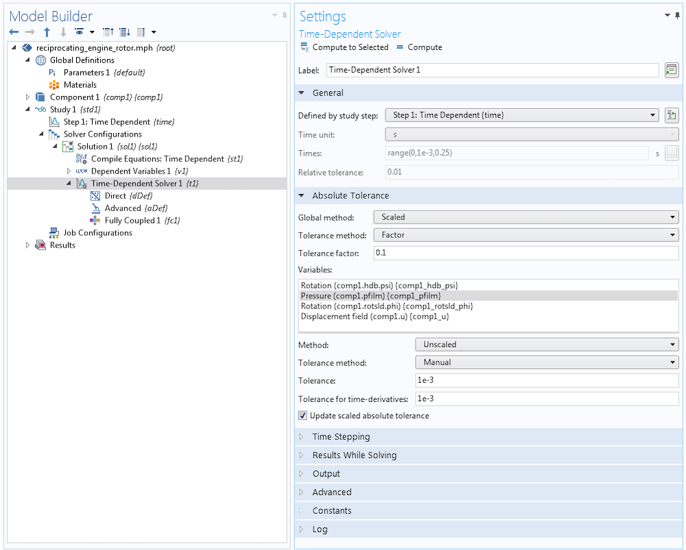
Next, we describe the time step selection method for the BDF scheme. For the time-dependent solver, the absolute and relative tolerances control the error in each integration step. The relative tolerance, R, is typically determined by the physics settings, but we can switch to manual control in the Time Dependent study step. The default value is R=0.01. The absolute tolerance, A, can be set in the Absolute Tolerance section of the Time-Dependent Solver. For the Factor option in Tolerance method, the absolute tolerance is the relative tolerance multiplied by the specified factor. The Manual option allows us to specify a detailed value where the default is A=0.001. The absolute tolerance can be applied individually to every field by using the Variables list.
Specifically, BDF computes an estimate of the local truncation error at the kth time step and requires the error estimate to satisfy the inequality \|\bar{e}_{k}\|_{\rm WRMS} < 1. In the time-stepping mechanism, there is an initial phase that is treated specially. For the first couple of steps, the step size \tau_k is doubled and the order is raised, taking the values q=1,2,3, … in every step until the local error test \|\bar{e}_{k}\|_{\rm WRMS} < 1 fails; the order q is reduced by a mechanism that checks the smoothness of the solution; or the order q reaches the maximum order, q=5. The choice of the order in the BDF scheme is based on the requirement that the scaled derivative norms |\tau^k U^{(k)}| are monotonically decreasing in k for k near q. These norms are again estimated using the fact that
The step and order selection begins with a test for monotonicity of T(q). A decreasing value of T(q) indicates that the solution is smooth and that the order can be increased. The order is decreased if T(q) increases with q. Otherwise, the order q is kept. Next, the local error test is performed, and if it fails, the step is redone at order q’=q and a new step size \tau’. The latter is based on the O(\tau^{q+1}) asymptotic behavior of \bar{e}_k. With \bar{e}_{k,\tau} > A + R |U|, we are requiring that for the corrected time step \tau’, at least \bar{e}_{k,\tau’} = A+R|U| holds true, which gives rise to the new time step \tau’. Via
we derive
where additional safety factors are used in the implementation.
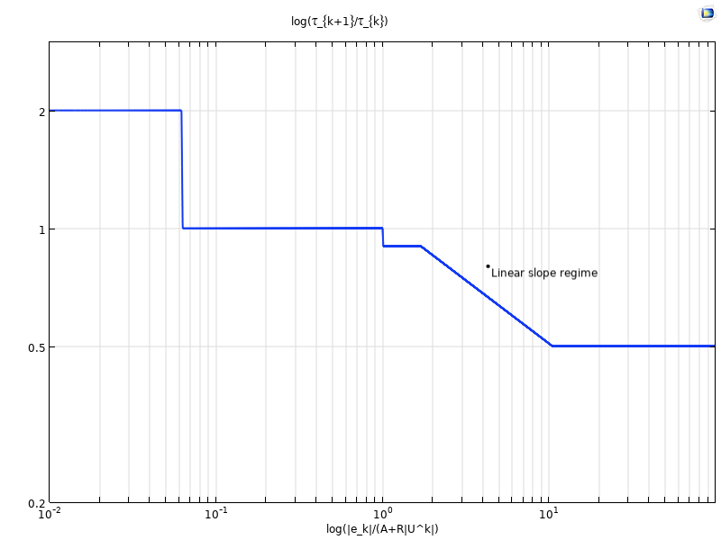
If the error is smaller than the allowed one, there is a so-called ”deadbeat” region where the time step is not increased until the error is 16 times smaller than the allowed one. Then, the time step is increased by a factor of two. Note that the determination of the time step is mostly regulated by limiters. The regulator is based on the given formula only in the linear slope regime. This regime is ruling when the estimated local errors are larger than what they should be and the time step needs to be decreased. In the figure below (in analogy to the corresponding figure in Ref. 1), you can identify the slope -1/(q+1) in the linear slope regime, where \log(\tau_{k+1}/\tau_{k}) is printed against \log(|\bar{e}_k|/(A+R|U^k|)) .

If the local error test passes, the step and the order for the next step are adjusted. There is no change in the order if it was changed in the previous step. If the last q+1 steps were taken at a constant order q<5 and a constant step size, BDF considers raising or decreasing the order. The order q is increased if T(q) is decreasing with q, and it is decreased if T(q) is increasing with q. More details and heuristics can be found in the documentation of the IDA solver in the Suite of Nonlinear and Differential/Algebraic Equation Solvers (SUNDIALS).
Concluding Thoughts on Automatic Time Step and Order Selection
In this blog post, we have discussed the automatic step size and order selection mechanism for the BDF time-stepping scheme. These mechanisms are designed to guarantee accuracy of the solution according to the prescribed tolerances at low costs and maximal robustness. In practice, we find that this mechanism can result in very small time steps and long simulation times. Too-small time steps and repeated failures of the time-dependent and nonlinear solver steps indicate that further tuning of the model configuration and solver settings might be required. We should also always make sure that the underlying model is well posed with a reasonable solution.
In an upcoming blog post, we will look at examples and discuss which solver settings can be adjusted in the case of too-small time steps. Stay tuned!
Further Reading
Get more details about solving time-dependent models by browsing the COMSOL Knowledge Base:
- BDF, Generalized Alpha, and Runge-Kutta Methods
- Solving time dependent models with inconsistent initial values
- Controlling the Time Dependent solver timesteps
Reference
- G. Söderlind, L. Wang, “Adaptive time-stepping and computational stability“, J. Comp. and Appl. Math., vol. 185, pp. 225–243, 2006.


Comments (1)
Mohammad Hdaib
May 20, 2021thank you so much