In this blog post, we will introduce the concept of shape optimization for adjusting part dimensions by using analytic sensitivity methods. If you have a single objective function that you want to improve, a set of geometric parameters that you want to change, as well as a set of constraints, then you can use the functionality of the Optimization Module and the Deformed Geometry interface in COMSOL Multiphysics to find the optimal structure without any remeshing. Let’s find out how!
Optimizing a Parallel Plate Capacitor Simulation
Let’s begin by referring back to a previous blog post on the computation of design sensitivities that shows how we can use the Deformed Geometry interface and the Sensitivity study to analytically evaluate the design sensitivities of a parallel plate capacitor. For that problem, we computed the change in the capacitance with respect to geometric and material property variations. We also computed the design sensitivities to geometric changes without altering the geometry or performing any remeshing. We now want to use that same framework to change the geometry of our capacitor with the objective of minimizing a particular quantity by using the functionality of the Optimization Module.
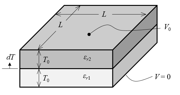
We start with a simple extension to the previous example: a parallel plate capacitor of side length L=1\ m with two dielectrics, \epsilon_{r1}=2, \epsilon_{r2}=4, each of the same initial thickness, T_0=0.1\ m. Further, we will neglect all fringing fields. This lets us model only the region between two parallel plates so that our computational model looks just like the figure shown below.

Schematic of a parallel plate capacitor with two dielectrics between the plates. Fringing fields are ignored.
This model can be built by sketching two geometric blocks of dimensions as described above. The Electrostatics physics interface allows us to apply a voltage and a Ground condition at the top and bottom faces as well as apply material dielectric properties. It is possible to compute the capacitance by integrating the electric energy density, as described in the previously mentioned blog post, and get a value of C_{computed}=118\ pF.
Now, let’s suppose that we want to design a 100 pF capacitor by changing the thicknesses of the two layers, without altering the overall dimensions of the device. This can be posed as an optimization problem:
That is, we want to get the capacitance to be as close to 100 pF as possible by varying the change in the dielectric thicknesses within limits such that neither dielectric is of zero thickness. The design parameter dT is the changing in the thicknesses of the two layers, as shown above. The objective function itself is formulated such that the absolute magnitude is on the order of unity. For numerical reasons, this form is preferred over (C_{computed}-100\ pF)^2 or the absolute value function: |C_{computed}-100\ pF|.
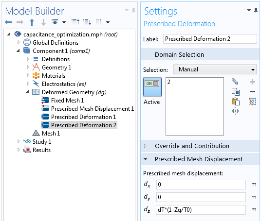
We can begin by defining the variation of the thickness of the dielectric layers using the Deformed Geometry interface. The Deformed Geometry interface is necessary because we want to compute the analytic sensitivities without having to remesh the geometry as we change the dimensions. Since we will be changing the sizes of the two dielectrics, we want to define these deformations as completely as possible. We will do this with a Prescribed Deformation domain feature, as shown in the screenshot below.
The capacitor itself is originally sketched such that it is centered at the origin so the original, undeformed part has a coordinate system: (Xg,Yg,Zg). For this simple Cartesian geometry, we can use this coordinate system to directly define the deformation as the thicknesses of the dielectric layers are changed. The deformations of the bottom and top layer are dT*(1+Zg/T0) and dT*(1-Zg/T0), respectively, where dT and T0 are Global Parameters.

The change in the thicknesses of the dielectric layers is controlled with a Prescribed Deformation feature.
Next, let’s look at the optimization user interface. For this simple problem, we can just add an Optimization feature to our study sequence, as shown in the screenshot below.
This minimization problem statement and scaling can be implemented entirely within the Optimization study node, as shown in the screenshot below. The relevant settings are the Objective Function, which is the expression (C_computed/100[pF]-1)^2, and the Control Parameter, dT, which has an initial value of 0[m]. The upper and lower limits are specified to prevent zero, or negative, thicknesses. Lastly, we apply a scaling to dT, the design parameter, based upon the original thickness, D, such that the optimized value will have an order of magnitude near unity.

The optimization solver settings.
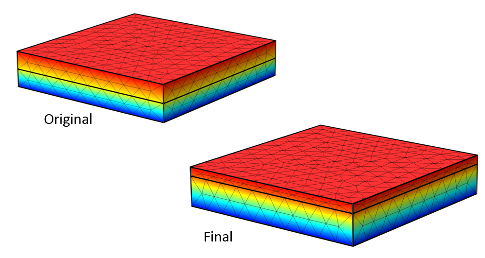
The SNOPT method is used to solve the optimization problem. Both the SNOPT and MMA methods use the analytically computed sensitivities, but SNOPT converges the fastest to within the default tolerance of 1E-6. The resultant device capacitance is 100 pF and the thickness of the dielectrics is D1 = 0.1542 m and D2 = 0.0458 m. The voltage field in the original model and the optimized structure are shown below, along with the finite element mesh. Observe that the finite element mesh is stretched and compressed, but that no remeshing has occurred.

The original and final structure. The voltage field and mesh are shown.
Closing Remarks on Shape Optimization and Deformed Geometry
We’ve looked at a fairly straightforward example of shape optimization, although with a little more effort, we could have found the solution to this problem by hand or by performing a parametric sweep. The geometric deformation demonstrated here is also quite simple. As you consider more complex geometries and more complex geometric changes, you will not always be able to directly use the undeformed spatial coordinates to define the deformation. In such cases, you will need to add equations to the model to help define the deformation. Of course, you may also want to consider more complex deformations, not just simple dimensional changes. We will cover this topic in an upcoming blog post on optimization.
In the meantime, if you have any questions about this technique and would like to use the Optimization Module for your design needs, please contact us.


Comments (10)
Fedai ?nan?r
January 24, 2016Great, please load the pdf file displaying how to make with details the simulation
Bridget Cunningham
January 25, 2016 COMSOL EmployeeHello,
Thank you for your comment.
PDF instructions are not included with every blog post. If you are having trouble following the instructions presented here, I would encourage you to reach out to the COMSOL support team for assistance.
Online support center: https://www.comsol.com/support
Email: support@comsol.com
Mahvash Afzal
March 30, 2017Very informative. Thanks for sharing. I didn’t understand one thing though: why are we defining deformation as dT*(1-Zg/T0). Can we define a deformation simply as dT such that dT varies fro 0 to say some value 0.02 [m], for example?
Walter Frei
March 30, 2017 COMSOL EmployeeHello Mahvash, The expressions “dT*(1-Zg/T0)” and “dT*(1+Zg/T0)” define the complete deformation of the two domains, as a function of Zg. We want to completely define the deformation, if possible, when using Deformed Geometry. Of course, of you want, you can also try out your approach and observe the differences.
Matheus Magalhães
February 21, 2018How can I run a Comsol V5.2 file in Comsol V.4.4? It is possible?
Thank you…
Caty Fairclough
March 1, 2018Hi Matheus,
Thanks for your comment.
For your question, please contact our Support team.
Online Support Center: https://www.comsol.com/support
Email: support@comsol.com
veerpal kaur brar
April 17, 2018How can I run a Comsol V5.2 file in Comsol V.4.4? It is possible?
Thank you…
Matheus Magalhães
July 5, 2018I don’t understood why the deformation of the bottom and top layers are dT*(1+Zg/T0) and dT*(1+Zg/T0), can someone help me? Thankss!!
Walter Frei
July 5, 2018 COMSOL EmployeeHello Matheus,
The deformations are:
dT*(1+Zg/T0) and dT*(1-Zg/T0)
Note the sign change in the two different domains.
I’d also like to point out that this blog is setting the stage for some more interesting topics:
https://www.comsol.com/blogs/designing-new-structures-with-shape-optimization/
https://www.comsol.com/blogs/how-to-optimize-the-spacing-of-electromagnetic-coils/
Best Regards,
Jingbin Zhao
August 3, 2023Thanks for sharing, very useful information for optimization study, I applied the similar concept in my model, and the control parameter has been constraint with lower bound 0.5, but it still begin from 0, and I got this error; Started at Aug 3, 2023, 8:19:56 PM.
Optimization solver (SNOPT)
Warning: The objective is only evaluated at the final time.
Number of optimization variables: 1.
Analytic gradient with the forward method.
Itns Major Minor Step nEval Error Objective
0 0 0 – 2 0 6.549e-07
Warning: Maximum number of model evaluations reached. Aborting as soon as possible.
I am wondering could you please sharing the model file? thanks in advance for your help!