Pressure vessels are designed to confine liquids or gases. These containers are used in nuclear plants, the chemical and petroleum industries, and even as water heaters in homes. In principle, the vessels’ internal pressure is much higher (or sometimes lower) than the ambient pressure, so the vessels must be carefully designed, as failure can result in severe damage. Today, we’ll explain how to use the Application Builder in the COMSOL Multiphysics® software to create an efficient and accurate design workflow.
The Geometry of a Pressure Vessel
To begin, let’s take a look at a common geometrical configuration for a pressure vessel.
Pressure vessels are made in different shapes and dimensions. Cylindrical shapes are a common choice due to the trade off between manufacturing cost and performance.
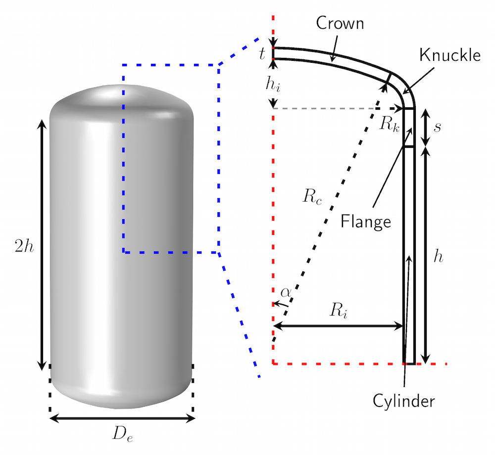
Typically, cylindrical pressure vessels are made out of a cylinder capped by two heads. Different shapes for the heads are available, with the torispherical head often selected. Torispherical heads are composed of a crown, a toroidal shape knuckle, and a straight flange.
The two most common torispherical heads in use are the Klöpper head and the Korboggen head. What differentiates these two heads is the geometric relationships that are used to design the crown and the knuckle dimensions. In a Klöpper head, $R_c = 2R_i$ and $R_k = 0.2 R_i$. In a Korboggen head, $R_c = 1.6 R_i$ and $R_k = 0.308 R_i$. Here, R_i is the radius of the cylindrical part of the vessel, $R_c$ is the crown radius, and $R_k$ is the knuckle radius.

Geometrical dimensions of a cylindrical pressure vessel with a torispherical head.
Now that we’ve got our geometry set up, let’s briefly discuss some important elements when it comes to material plasticity and how it affects the design of pressure vessels.
A Brief Introduction to Material Plasticity
Rolled metal sheets are commonly used in the manufacturing of pressure vessels. Most designs are such that a material operates within the elastic limit, as is the case when moderately large stresses act in them. The material then exhibits a deformation that is proportional to the load. Further, the shape returns to the original configuration once the force is removed. However, if the force exceeds a limiting value known as the yield limit, the body does not return to its original shape, even when the loading is completely removed. It instead remains partly deformed.
In such a case, we say that the body has undergone plastic deformation. For a pressure vessel made of rolled steel, this yield stress can be of the order of 500 MPa. Due to the high internal pressure, parts of the vessel in the vicinity of the transition at the knuckle may exceed the elastic limit and operate in plastic conditions.
In this example, a rather sophisticated plasticity model is incorporated into the mix: Hill’s orthotropic plasticity. For rolled steel plates, the yield limit in different directions is not the same due to the rolling process. Such behavior can be captured using Hill’s orthotropic plasticity model. The Nonlinear Structural Materials Module, an add-on to the Structural Mechanics Module and COMSOL Multiphysics, is the internal backbone for the elastoplastic analyses of pressure vessels. Now, with the Application Builder, we can make such physics available in an easy-to-use app that can be accessed by a wide range of users.
Get Inspired by Our Demo App: Stress Analysis of a Pressure Vessel
When building a simulation app, your task as the designer is to identify the important parameters that influence the outcome of the simulation. Once these are determined, the flexibility and functionality of the Application Builder enables you to create a specialized user interface (UI) that includes only those selected parameters. End-users can then easily run simulation tests and interpret the results without having to understand how the underlying physics are actually implemented within COMSOL Multiphysics.
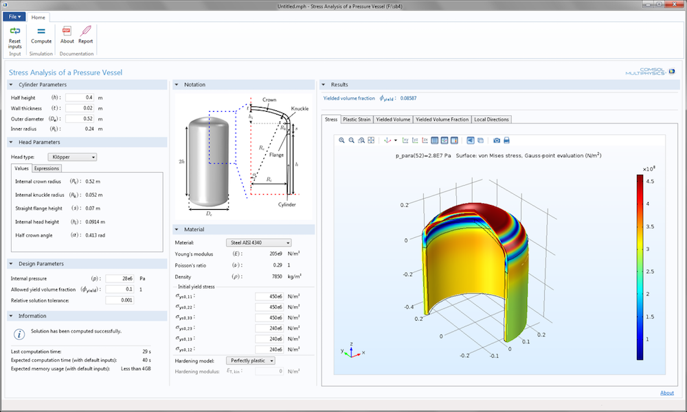
Knowing that we are going to perform plasticity analyses on a pressure vessel, the question becomes this: Which parameters are relevant for selection as user inputs? The options to vary the geometry and material properties are obvious candidates. Another desirable feature is the ability to modify the operating conditions; for instance, the operating pressure inside the vessel and allowable yield fraction values based on safety considerations. Such parameters are included as inputs in our app and can be entered through the customized UI.

The UI of the Stress Analysis of a Pressure Vessel app.
After computation, the quantities of interest can be displayed in predefined plots:
- Von Mises equivalent stress
- Plastic strains
- Yielded region
- Yielded volume fraction as a function of the internal pressure
The Stress Analysis of a Pressure Vessel app is just one example of how the Application Builder can be used to encapsulate complex simulation studies within a user-friendly layout. Suppose, for instance, that you want to meet a certain safety condition for a given operating pressure inside the vessel. With an app, it is easy to alter the geometry and material properties to identify the right combination that works within the safety limits. Users are able to modify the parameters in the UI without having to understand the working principles of COMSOL Multiphysics.
With apps, as we’ve highlighted here, performing repeated computations with varying parameter settings is faster and easier than ever before. Start building apps today and experience how they can optimize your own design workflow.
Start Building Simulation Apps
Learn how to build simulation applications of a COMSOL Multiphysics model using the Application Builder by checking out our Learning Center course on building and running simulation apps.


Comments (6)
MANIBHUSHAN KUMAR
September 15, 2024Where to put Fixed constrain? When we have cylindrical shape body.
Henrik Sönnerlind
September 20, 2024 COMSOL EmployeeFor axisymmetric structures, it is not necessary to have a fixed point to keep a structure stable. In this example, a symmetry condition in the axial direction will be sufficient.
MANIBHUSHAN KUMAR
September 21, 2024Sir, I am working on pressure cooker. where I gave used 3D model for simulation, not the axisymmetric, due to some reason. If I set the bottom portion as a fixed constraint, the output will only show the maximum Von Mises stress there. which, in my opinion, is incorrect. Could you advise me on what to do in this situation?
Evan Sisler
December 12, 2024 COMSOL EmployeeHi! For additional assistance with your modeling problem, please contact our Support team using your COMSOL Access account at https://www.comsol.com/support.
MANIBHUSHAN KUMAR
September 21, 2024Would you please give the simulation’s mph file? if it is feasible. It will be very beneficial for my work.
Gustav Schmied
October 16, 2024@MANIBHUSHAN KUMAR
Look at:
https://www.comsol.com/model/pressurized-orthotropic-container-12669
and
https://www.comsol.com/model/pressurized-orthotropic-container-shell-version-78091