
Have you ever wanted to write out mesh and analysis data from COMSOL Multiphysics into a text file? You may want to do this when passing information to another software program or even just into a spreadsheet. You often want to customize the exact format in which such data is written, depending upon the needs of the other tools with which you are working. This is very easy to do with the Application Builder. Let’s find out how!
Working Across Software Platforms
Suppose you are working on a COMSOL Multiphysics model and performing thermal analyses of systems. You’re working with a team of people performing other types of analyses. Your colleagues aren’t quite as lucky as you and don’t get to use COMSOL Multiphysics, but they still need access to your modeling results. Fortunately, you can quickly convert your analysis data into a very specific text file format that can be read by the software tool that your colleagues are using.
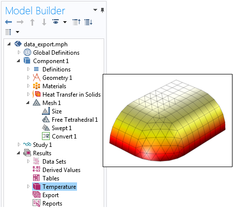
A simple COMSOL Multiphysics thermal model that has different element types.
Now, let’s suppose that you’re performing steady-state thermal analyses of models containing all kinds of different elements, including tetrahedral; pyramidal; prismatic; and hexahedral (brick) types, as shown above. Let’s further suppose that the software tool we will be reading the data into requires that we use a linear discretization, meaning that we need to write out a temperature at each of the nodes (vertices) defining the corners of the elements and a linear interpolation of temperature will be used to compute the temperature fields within the elements. Thus, we need to write out all of the vertex locations; the temperature data at each of these vertices; and a description of which vertices define each element, and how.
There are, of course, many different ways in which this kind of information can be written. For the purposes of today’s blog post, we will assume a simple comma-delimited format, a generic sample of which is shown below.
N, 1, 0.0, 0.0, 0.0
...
N, 1000, 10.0, 10.0, 10.0
D, 1, 332.0
...
D, 1000, 343.0
TET, 1, 2, 4, 6, 3
...
TET, 100, 42, 43, 41, 45
PYR, 101, 47, 48, 41, 40, 44
...
PRISM, 201, 66, 67, 65, 72, 74, 73
...
HEX, 301, 81, 82, 83, 84, 91, 92, 93, 94
...
Let’s take a look at what these various lines mean. All lines begin with a text string denoting what kind of information is on that line and the information is delimited by commas into various fields. On the first line, we have vertex (nodal) location information:
N, 1, 0.0, 0.0, 0.0
The first field after the N character is the node number, which is arbitrary, and the second, third, and fourth fields are the x-, y-, and z-locations of that node, so our first node is at the global origin. In the above sample, there are one thousand nodes in all.
Next, the computed temperature data at each node location is written on a separate line:
D, 1, 332.0
where the first field after the D character is the node number and the second field is the temperature at that node location.
The remaining lines give information about the elements and how they are defined by the nodes. Let’s start by looking at the first element definition:
TET, 1, 2, 4, 6, 3
This line defines a tetrahedral (TET) element. The first field is the element number and the next four fields tell us which nodes define the tetrahedra. Here, nodes 2, 4, 6, and 3 are nodes 1 through 4 of the element. Such information is also known as the element connectivity and to understand this, let’s look at an illustration of our element.
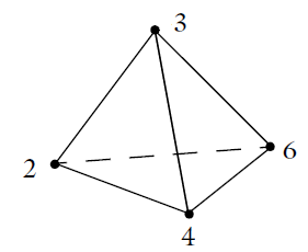
A tetrahedral element is defined by four nodes.
For our tetrahedral element example, nodes 2, 4, and 6 are the first three nodes. If we use the right-hand rule and follow these three nodes around in order, we get a vector that points in the direction of the fourth node, node number 3. The element ordering for all of the three-dimensional element types is shown below.
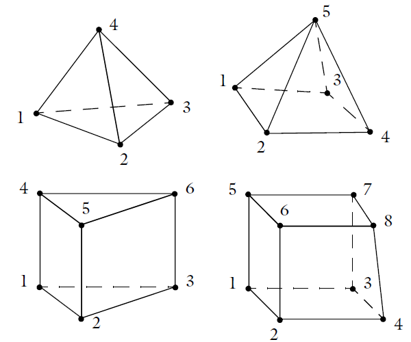
Element number conventions for the four different types of 3D elements.
Now that we understand the data format that we need to write out to our text file, let’s look at how this can be done with the Application Builder.
Writing Out Data Using the Application Builder
We begin our app development with an existing 3D model that already has a steady-state temperature solution computed, as shown earlier. To develop the app, switch to the Application Builder, where we will define the graphical user interface and write the data processing code behind our app. Our interface will be very simple, with just a button that calls a method and a message log that will display some information. The app will do only one thing: When the user clicks on the button, the data format described above is written to a text file and a summary of what was written will be shown in the message log.
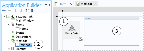
Our app has a button (1) that calls a method (2), which writes the mesh and solution data to a file and writes some statistics to the message log (3).
The method contains all of the data processing code and is shown below with line numbers added and text strings in red.
1   StringBuffer FileB = new StringBuffer();
2  double[][] d_Vtx = model.mesh("mesh1").getVertex();
3  String[][] s_Vtx = toString(d_Vtx);
4  for (int m = 0; m < s_Vtx[0].length; m++) {
5    FileB.append("N, "+(m+1)+", "+s_Vtx[0][m]+", "+s_Vtx[1][m]+", "+s_Vtx[2][m]+"\n");
6  }
7  model.result().numerical().create("interp", "Interp").setInterpolationCoordinates(d_Vtx);
8  model.result().numerical("interp").set("expr", "T");
9  double[][][] AllData = model.result().numerical("interp").getData();
10  model.result().numerical().remove("interp");
11 for (int m = 0; m < AllData[0][0].length; m++) {
12   FileB.append("D, "+(m+1)+", "+AllData[0][0][m]+"\n");
13 }
14 int[][] Ei;
15 int numTets = model.mesh("mesh1").getNumElem("tet");
16 if (numTets > 0) {
17   Ei = model.mesh("mesh1").getElem("tet");
18   for (int m = 0; m < numTets; m++) {
19     FileB.append("TET, "+(m+1)+", "+(Ei[0][m]+1)+", "+(Ei[1][m]+1)+", "+(Ei[2][m]+1)+", "+(Ei[3][m]+1)+"\n");
20   }
21 }
22 int numPyrs = model.mesh("mesh1").getNumElem("pyr");
23 if (numPyrs > 0) {
24   Ei = model.mesh("mesh1").getElem("pyr");
25   for (int m = 0; m < numPyrs; m++) {
26     FileB.append("PYR, "+(m+1+numTets)+", "+(Ei[0][m]+1)+", "+(Ei[1][m]+1)+", "+(Ei[2][m]+1)+", "+(Ei[3][m]+1)+", "+(Ei[4][m]+1)+"\n");
27   }
28 }
29 int numPrisms = model.mesh("mesh1").getNumElem("prism");
30 if (numPrisms > 0) {
31   Ei = model.mesh("mesh1").getElem("prism");
32   for (int m = 0; m < numPrisms; m++) {
32     FileB.append("PRISM, "+(m+1+numTets+numPyrs)+", "+(Ei[0][m]+1)+", "+(Ei[1][m]+1)+", "+(Ei[2][m]+1)+", "+(Ei[3][m]+1)+", "+(Ei[4][m]+1)+", "+(Ei[5][m]+1)+"\n");
34   }
35 }
36 int numHexes = model.mesh("mesh1").getNumElem("hex");
37 if (numHexes > 0) {
38   Ei = model.mesh("mesh1").getElem("hex");
39   for (int m = 0; m < numHexes; m++) {
40     FileB.append("HEX, "+(m+1+numTets+numPyrs+numPrisms)+", "+(Ei[0][m]+1)+", "+(Ei[1][m]+1)+", "+(Ei[2][m]+1)+", "+(Ei[3][m]+1)+", "+(Ei[4][m]+1)+", "+(Ei[5][m]+1)+", "+(Ei[6][m]+1)+", "+(Ei[7][m]+1)+"\n");
41   }
42 }
43 writeFile("user:///output.txt", FileB.toString());
44 message("Data written to file output.txt in the user directory.");
45 message(s_Vtx[0].length+" Nodes\n"+numTets+" Tetrahedral Elements\n"+numPyrs+" Pyramid Elements\n"+numPrisms+" Prismatic Elements\n"+numHexes+" Hexahedral Elements\n");
Let’s go through this method line-by-line.
- Creates a string buffer into which we will store the data that will get written to the file.
- Extracts all of the mesh vertex locations from the model and puts the data into a 2D array of doubles.
- Converts the mesh location numerical data into string data, since it will be written out to a text file.
- Starts a for-loop that will iterate over all node locations.
- Appends a line for each node to the string buffer, with the node index and xyz-locations.
- Closes the for-loop over nodes.
- Sets up an interpolation feature to extract the data at the previously extracted node point locations.
- Sets the expression to evaluate at these node points. In this case, the variable “T” means that we are extracting temperature.
- Using the interpolation feature, extracts all of the temperature data. This gets stored in a 3D array of doubles.
- Removes the interpolation feature, since it is no longer needed.
- Sets up a for-loop over all of the extracted data. Since we are only extracting one field (temperature) and are assuming only one solution set exists in our model, we only need to index over the last dimension of our array.
- Appends a data line to the string buffer, with the node number and the value of temperature at that node.
- Closes the for-loop over all of the output data.
- Initializes an empty 2D array that stores the element index data.
- Extracts the number of tetrahedral elements from the model.
- Checks if there are any tetrahedral elements to write out.
- Extracts the tetrahedral element connectivity data from the model.
- Sets up a for-loop over all of the tetrahedral elements.
- Appends a line for each tetrahedral element to the string buffer, with the element number and the node numbers.
- Closes the loop over all tetrahedral elements.
- Closes the if-statement that checks if there are any tetrahedral elements.
Lines 22 through 42 simply repeat the functionality of lines 15 through 21 for the other element types. Note that the element numbers are incremented based upon all previous element numbers. Also, throughout this method, the indices of all nodes are incremented by one. This is because COMSOL Multiphysics internally starts all indices at zero, but in our desired output format, we want to start all node and element indices at one. The entire string buffer is converted to a string and written to the file on line 43. On lines 44 and 45, some information is printed to the message log.
The file that is written out is called output.txt and is found in the user directory. The location of the directory on the disk is specified in the software preferences when you go to File Menu > Preferences > Files > Application files, as shown in the screenshot below. You can change the directory as desired.

The location of the output files is specified in the software preferences.
And with that, our method is complete. In the screenshot below, we can see our application in action.
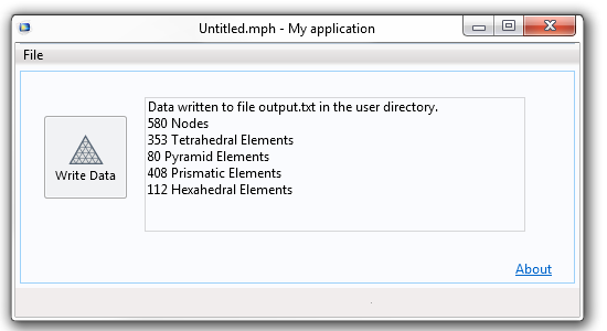
The application reports what has been written to the file.
Closing Remarks on Exporting Data with the Application Builder
We have demonstrated how to create a very simple app that writes out the mesh and results from a COMSOL Multiphysics steady-state thermal simulation. You can simply copy the data from the app and paste it into a text file or spreadsheet. There is, of course, a lot more sophistication that we could build into this app, including:
- Writing out multiple data sets that might represent different load cases or different times from a transient simulation.
- Formatting the data into a fixed-format file type.
- Writing out higher-order element types and interpolation schemes.
- Writing out vector data, or data that is discontinuous between elements.
Of course, we won’t address all of these cases right now, but if you’re interested in adding such modifications into your own customized app, here are some resources to get you started:
- Download the Introduction to Application Builder manual
- Watch videos designed to help you learn the basics of using the Application Builder and COMSOL Server™
- Browse our blog posts to see how simulation apps are used in a range of applications
Seeking more information on how to build a specific type of app or have other modeling inquiries? Contact us.


Comments (5)
Nhan Nguyen
May 6, 2016Thanks a lot ! An amazing paper!
Krisztián Gadó
March 11, 2018Hi!
Thanks a lot for this guid!!
I have 2 question:
1. I want export only some parts of mesh, how can i do that?
2. What about time-dependent variables?
For example: I have an asynchronous motor and i want to export the magnetic flux density in each time step, but only on the stator nodes, how can i do that?
Caty Fairclough
March 29, 2018Hi Krisztián,
Thanks for your comment!
For your questions, please contact our Support team.
Online Support Center: https://www.comsol.com/support
Email: support@comsol.com
Mervenaz Sahin
February 11, 2020Hello,
Where can we export the data given below, the one you mentioned in here?
I need to extract the connectivity matrix or the node coordinates for every element’s nodes.
Thank you,
N, 1, 0.0, 0.0, 0.0
…
N, 1000, 10.0, 10.0, 10.0
D, 1, 332.0
…
D, 1000, 343.0
TET, 1, 2, 4, 6, 3
…
Sören
September 2, 2021Thanks for this (old) blog. 🙂
I wonder how to extract all nodes for a quadratic mesh?
They is no change in the nodes number if I change the discretization to quadratic.