
Adjusting the focal length of a camera lens allows you to change your angle of view. Miniature lenses can achieve this change by using a method called electrowetting. Electrowetting involves changing the balance of forces at a contact point of a free surface and a solid by applying a voltage. However, focus is not obtained immediately due to oscillations in the free surface. Here, we investigate the optimal viscosity for critically damping the free surface when a voltage is applied.
A Quick Introduction to Focal Length
Imagine that you’re taking a photo and zooming in and out to see what looks best. In this moment, you are using a variable-focus lens to change the focal length of your camera. Focal length is the distance between the optical center or point of convergence of your lens and your camera’s sensor when a subject is in focus.
A shorter focal length yields a wider angle of view and thus a zoomed out view of your subject. A longer focal length provides a zoomed in and narrow angle of view.


Left: A shorter focal length. Right: A longer focal length.
In order to adjust their focal length, traditional variable-focus lenses use moving parts that may not function on a miniature scale. Instead, miniature lenses can use alternative processes such as electrowetting to change their focal length.
Developing a Miniature Fluid Lens Using Electrowetting
Electrowetting is the process of applying a voltage between a conducting fluid and a solid surface in order to modify the balance of forces at the contact point. In the case of a lens, this can change the meniscus shape of a liquid and so alter the focal length of the lens.
For example, let’s look at a tutorial model based on an electrowetting lens developed by the Philips FluidFocus team.
This tutorial model consists of a sealed chamber with two immiscible liquids: a lower conducting fluid and an upper insulating fluid. Both fluids have a matching density and viscosity. The tutorial also utilizes a technique called electrowetting on dielectric (EWOD), which involves using a thin dielectric deposited onto a conducting layer as the solid surface.
When the voltage applied to the conducting liquid of the lens is increased, the meniscus curvature changes from convex to concave, as pictured below.
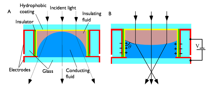
A change in curvature due to electrowetting. When a voltage is applied, the curvature changes from A to B. Image credit: Philips.
This change occurs because the wetting properties of the surface are altered by the voltage, causing the fluid to change position in response. The modified curvature changes the focal length, which allows us to use the meniscus between these two liquids as a variable-focus optical lens.
Although the design we’ve described so far is functional, it may not allow you to quickly change focal lengths. This is an issue because you don’t want to wait for your camera lens to adjust positions every time you need to change the focal length. To avoid this, we can optimize the electrowetting process to create a lens with the fastest possible response time.
Optimizing an Electrowetting Lens with Simulation
As we switch the voltage applied to the electrowetting lens, the contact angle of the fluid can change abruptly. We see this change happening in the following photos from Philips.

The change in meniscus shape for the following voltages: C: 0 V, D: 100 V , and E: 120 V. Image credit: Philips.
The movement creates a disturbance that produces capillary waves on the interface. This may result in oscillations that take time to decay. For instance, in this tutorial model, higher-order modes are still visible 2 ms after the voltage is switched from 100 V to 120 V.
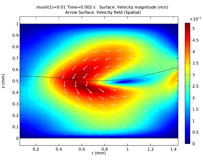
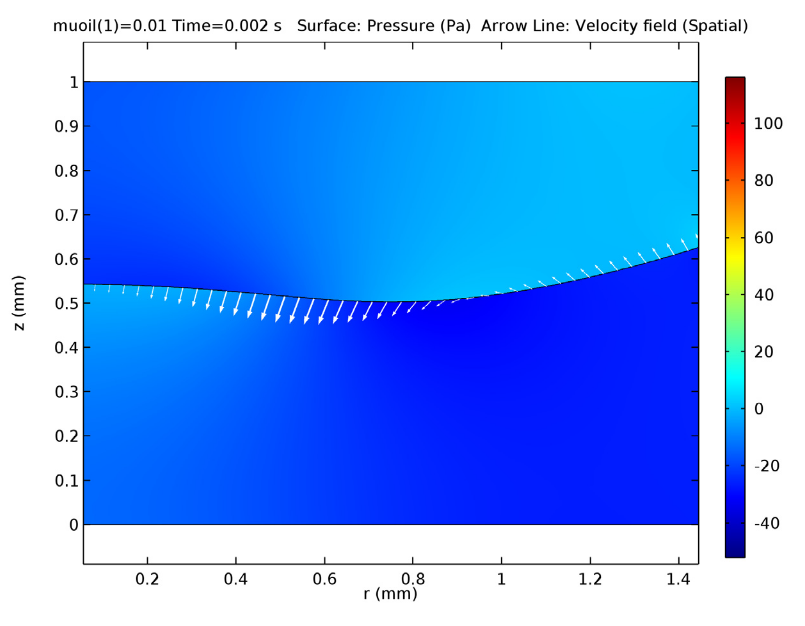
Images show the electrowetting lens 2 ms after the voltage changed from 100 V to 120 V. In both cases, the viscosity of the insulating fluid is 10 mPa·s. Left: Fluid velocity magnitude (color) and direction (arrows). Right: Pressure in fluid (color) and boundary velocity (arrows).
To optimize the lens, we want to facilitate quick focal length shifting by minimizing the oscillations of the meniscus that occur during this process. Therefore, the system needs to be critically damped to achieve the fastest possible response time.
In order to accomplish this, we can change the damping of the insulating fluid by adjusting its viscosity. This tutorial uses COMSOL Multiphysics® software Two-phase Flow, Moving Mesh interface to accurately model the flow of two different fluids and test different values of viscosity.
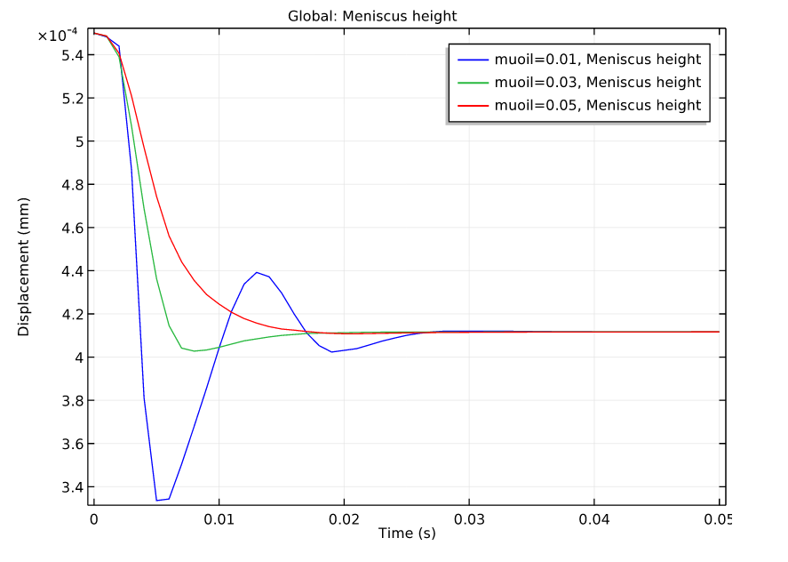
Comparing different values of viscosity by plotting the location of the center of the meniscus against time.
Of the tested viscosity values, it appears that 50 mPa·s is the closest to being critically damped, and is therefore the optimal viscosity for the insulating fluid of an electrowetting lens.
The Philips FluidFocus team used this interface tracking method in their own numerical model. With this, they were able to develop a miniature electrowetting lens that can change its focal length over a large range.
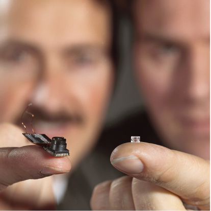
The PHILIPS® electrowetting lens and a camera that can contain the lens. Image credit: Philips.
You can test different viscosity values and analyze the physics of an electrowetting lens yourself by downloading the tutorial model.
Further Reading
- Learn about COMSOL Multiphysics multiphase flow interfaces
- Read more blog posts about microfluidics
PHILIPS is a registered trademark of Koninklijke Philips N.V


Comments (1)
James Kissinger
August 7, 2019Hi
How do I get a viscosity change in the comsol as an output?
I have a magnetic field around which there is a special fluid. I want to get the effect of the magnetic intensity on the viscosity of this liquid
please help me.
Please email me your answer
james kissinger