Today, guest blogger Dr. Qinghua Lei joins us to discuss a new method for modeling fully coupled hydromechanical processes in fractured media.
Understanding the coupling between solid deformation and fluid flow in fractured geological media is of central importance for resolving many core issues in geoscience and geotechnical engineering, such as underground excavation, hydrocarbon extraction, carbon sequestration, geothermal production, and waste disposition. This blog post describes a novel approach for modeling fully coupled hydromechanical processes in fractured media based on the COMSOL Multiphysics® software.
Why Use COMSOL Multiphysics® for Hydromechanical Modeling?
Generally speaking, there are two major challenges in modeling coupled hydromechanical processes in fractured media. One is the representation of the discontinuous nature of geological media embedded with numerous natural fractures, which ubiquitously exist over many different length scales and often dominate the bulk behavior of the system (Ref. 2). Second is the computation of hydromechanical coupling mechanisms involving both direct coupling (i.e., interaction between the solid and fluid fields) and indirect coupling (i.e., alteration of rock/fracture properties).
Over the past years, a large number of commercial software packages and open-source research codes have been developed that are aiming to tackle these challenges. However, many of them have to compute the fluid and solid equations using different solvers such that coupling has to be implemented via an extra processing step, which is neither convenient nor efficient. In addition, most of the existing codes cannot really capture both direct and indirect couplings at the same time and thus assumptions or simplifications often have to be made.
The use of COMSOL Multiphysics is motivated by its exceptional capabilities of:
- Simultaneously solving multiphysics equations to achieve direct couplings
- Defining model parameters as a function of other field variables to achieve indirect couplings
- Explicitly representing discrete fractures and solving physical processes (e.g., fracture flow and fracture deformation) within them
Below, we elucidate the procedures of building numerical models in COMSOL Multiphysics for fully coupled hydromechanical modeling of fractured media, followed by some simulation examples.
Model Procedures
Three main steps are involved in conducting the numerical simulations in COMSOL Multiphysics.
Step 1: Generation of Model Geometry and Mesh
First, discrete fracture networks geometrically represented as lines/polylines can be constructed using CAD software like AutoCAD® or Rhinoceros®. The geometry data are then exported as DXF™ files that can be directly imported into COMSOL Multiphysics. This step can also be accomplished in MATLAB® to generate synthetic fracture networks following prescribed probability distributions and export them to DXF™.
Tip: You can also use the Discrete Fracture Network add-in to create randomized fractures in an existing geometry directly inside COMSOL Multiphysics, as described in this 3D example of a fractured reservoir.
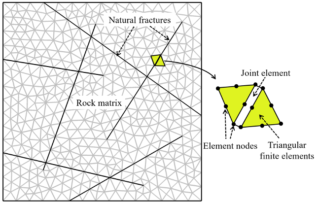
After the geometry is imported, we discretize the domain using an unstructured grid of triangular finite elements (via a Delaunay tessellation), where natural fractures are represented by joint elements embedded in between neighboring finite elements (Fig. 1).

Figure. 1. A schematic showing the model discretization using an unstructured grid of triangular finite elements, where natural fractures are represented by joint elements embedded in between neighboring finite elements.
Step 2: Model Setup and Definition of Material Properties, Coupling Parameters, and Boundary Conditions
We use the Solid Mechanics and Darcy’s Law interfaces in COMSOL Multiphysics to model the hydromechanical processes in fractured media. We activate the Poroelasticity interface to achieve the direct coupling between the solid and fluid equations. We define material properties and constitutive equations for both the rock matrix and fractures. Some of the rock/fracture properties, such as porosity, storativity, and permeability, are defined as a function of the local stress/pressure state to achieve indirect coupling. We also define the mechanical and hydraulic boundary conditions.
Step 3: Calculation of the Solution
We run the model in two consecutive stages. In the first stage, the system reaches an initial equilibrium (via a ramped loading) under the given in situ stress and pressure conditions. Then, in the second stage, we simulate the response of the system subject to engineering activities such as fluid injection or underground excavation.
Simulation Examples
Example 1: Fluid Injection in Fractured Rocks
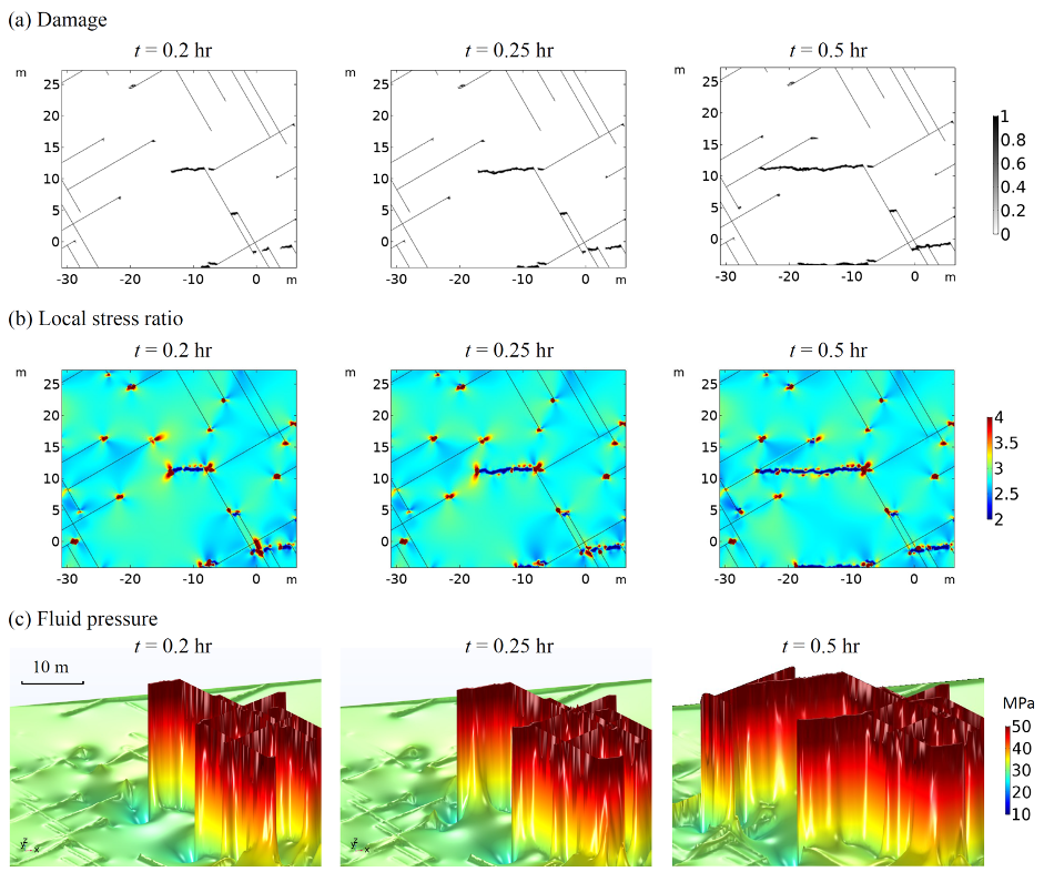
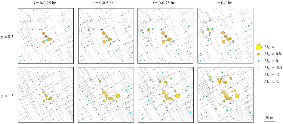
We apply the model to simulate the hydromechanical behavior of fractured rocks subject to fluid injection (Ref. 1). The model can realistically capture the pressure diffusion in fractured porous media and brittle, failure-induced damage in intact rocks as well as the important impact of fracture configuration on hydromechanical processes (Fig. 2). The model also allows us to visually inspect the detailed evolution of damage, stress, and pressure fields in the fractured rock and further investigate the fundamental control of poroelasticity on driving new damage propagation in the system (Fig. 3). Based on the simulation results, we can also analyze the spatiotemporal evolution of induced seismicity caused by brittle failure of intact rocks and/or frictional sliding of natural fractures (Fig. 4).
Figure. 2. Pressure evolution and damage propagation in fractured rocks during fluid injection.

Figure. 3. Inspection of the distributions of (a) damage; (b) stress ratio (i.e., ratio of the local maximum principal stress to the local minimum one); and (c) fluid pressure (visualized via a height expression) in a local region of the fractured rock.

Figure. 4. Spatial distribution and evolution of induced seismic events in the fractured rocks with a low and high fracture density of χ = 0.5 and 1.5, respectively.
Example 2: Underground Excavation in Fractured Rocks
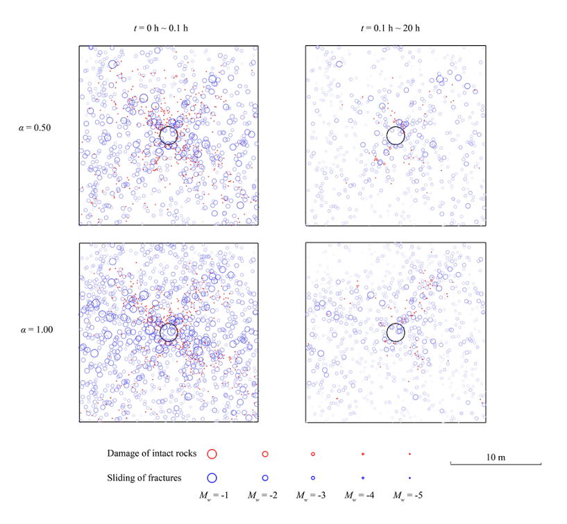
The model can also be applied to simulate the excavation-induced perturbation in fractured rocks and the resulting transient hydromechanical behavior (Ref. 4). We capture conspicuous pressure variation and diffusion as a result of excavation (for time t = 0-0.1 h) and subsequent drainage (for time t = 0.1~20 h) processes, together with stress alteration and damage evolution (Fig. 5). We illustrate the important role of hydromechanical coupling by performing a sensitivity analysis of the Biot coefficient. The results reveal that with a higher Biot coefficient (or, say, a stronger coupling), the excavation tends to cause a more uneven pressure field via poroelasticity as well as more rock damages and fracture displacements. The excavation and drainage stages both induce seismic events related to brittle damage of the rock matrix and/or frictional sliding of natural fractures (Fig. 6).
Figure. 5. Pressure, stress, and damage evolution in fractured rocks during and after excavation.

Figure. 6. Spatial distribution of seismic events in the fractured rocks with different Biot coefficients α during the excavation (left panel) and the drainage (right panel) stages.
In addition to the hydromechanical model described above, we have also developed a fully coupled thermohydromechanical model to simulate the performance of fractured geothermal reservoirs during long-term water circulation and heat production (Ref. 3).
References
- Q. Lei et al., “Modelling fluid injection-induced fracture activation, damage growth, seismicity occurrence and connectivity change in naturally fractured rocks”, International Journal of Rock Mechanics and Mining Sciences, no. 138, vol. 104598, 2021.
- Q. Lei et al., “The use of discrete fracture networks for modelling coupled geomechanical and hydrological behaviour of fractured rocks”, Computers and Geotechnics, no. 85, pp. 151–176, 2017.
- Z. Sun et al., “Combined effects of thermal perturbation and in-situ stress on heat transfer in fractured geothermal reservoirs”, Rock Mechanics and Rock Engineering, no. 54, pp. 2165–2181, 2021.
- C. Zhao et al., “Role of hydro-mechanical coupling in excavation-induced damage propagation, fracture deformation and microseismicity evolution in naturally fractured rocks”, Engineering Geology, no. 289, vol. 106169, 2021.
About the Author
Dr. Qinghua Lei is a lecturer and senior scientist at the Department of Earth Sciences, ETH Zürich, Switzerland. He holds a BSc (2009) and a MSc (2012) in civil engineering from Tongji University, China, and a PhD (2016) in rock mechanics from Imperial College London, UK. Dr. Lei is the recipient of the Rocha Medal from the International Society for Rock Mechanics and Rock Engineering (ISRM) as well as the NGW Cook PhD Dissertation Award and the Rock Mechanics Research Award from the American Rock Mechanics Association (ARMA). Dr. Lei’s research interests include rock mechanics, coupled processes, fracture characterization, multiphase flow, seismic waves, induced seismicity, and slope stability. He is the secretary general of the ISRM Commission on Thermal-Hydro-Mechanical-Chemical Processes in Fractured Rock, an ARMA Future Leader, and a founding member of the ARMA Underground Storage & Utilization Technical Committee.
Autodesk, the Autodesk logo, AutoCAD, and DXF are registered trademarks or trademarks of Autodesk, Inc., and/or its subsidiaries and/or affiliates in the USA and/or other countries.
Rhinoceros is a registered trademark of TLM, Inc. DBA Robert McNeel & Associates Corporation.
MATLAB is a registered trademark of The MathWorks, Inc.


Comments (3)
Matthew Becker
October 29, 2021This is fantastic work. Are the model files available?
El Mustapha Guellal
June 3, 2024Hello, I am a master’s student researching induced seismicity in fault zones. I believe your model could greatly assist in my thesis. However, I’ve encountered difficulties implementing your equations and recreating the model independently. Could you please share the model files or offer additional guidance on achieving equilibrium within the system and the underlying physics you’ve employed? Thank you in advance.
Zafar Khan
December 19, 2024This is very good work. Are the model files available?