The use of geothermal heat for building climatization is a cost-effective and sustainable method. In part three of our Geothermal Energy series, we will have a closer look at shallow tubing heat collectors. An accurate prediction of their thermal performance, considering both the piping layout and local thermal properties, turns out to be an appropriate job for the Pipe Flow Module.
Geothermal Heat Collectors
Modern building construction requires efficient climate control, preferably using sustainable energy resources. Such resources can be solar collector systems for warm-water support or ambient air or geothermal-based heat pump systems that can be used for cooling in the summer and heating in the winter.
The geothermal applications mostly consist of pipe installations with water or brine as fluid to provide the heat exchange between the subsurface and a heat pump. There are two main types of these so-called closed-loop systems: vertical borehole heat exchangers (BHEs), which are installed in boreholes (see part 1 of this series); and horizontal heat collectors, which are deposited on large areas and in very shallow depths of only one or two meters.
While the vertical BHEs are often simplified as infinite thermal line sources or sinks, the horizontal systems are more complicated from a modeling point of view. This is because they have to be arranged in patterns to cover large surface areas, and the use of this simplification does not match anymore. The total length of the pipes can easily reach 100 meters or more. The flow regime is preferably turbulent because of the resulting lower thermal resistivity between the fluid and the subsurface. You can imagine that a CFD simulation approach of systems with these dimensions is a challenge (despite the computational performance of modern HPC clusters). Fortunately, there is a solution for this kind of task.
Let’s have a look at how the Pipe Flow Module can be used in the growing sector of geothermal heat collector systems.
Concentrate on the Essentials with the Pipe Flow Module
Thankfully, we do not have to care about the computational difficulties that may arise when simulating long pipe systems. The Pipe Flow Module provides all necessary capabilities to calculate pressure drops, velocities, and foremost — the heat transport between the pipe fluid and the subsurface, using prescribed 3D curved-edge correlation functions. All we need to do is to define the inlet conditions (temperature, velocity) and the pipe, fluid, and subsurface properties. Therefore, we can completely focus on questions like, “What do you think is the best horizontal pipe arrangement underneath your garden?”
Let’s find out.
Example Model: Use Your Garden as a Heat Source
The heat transfer example, provided in a recent blog post, shows how a prescribed heat extraction rate can be realized in the form of a numerically-calculated inlet temperature boundary condition. By doing so, any desired heat extraction rate can be given and the corresponding inlet temperature can be computed. Assuming that the fluid properties are temperature-independent, a simplified version of the inlet temperature can be written as:
(1)
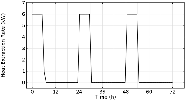
Thus, it is a function of the outlet temperature (T_{out}), density (\rho_f), heat capacity (C_{p,f}), and volumetric flow rate (\dot{V}) of the working fluid in the pipes. The temperature difference between the inlet and outlet temperature is controlled via the heat extracted by the heat pump, P(t), which is a function of time because heat pumps (for house heating purposes) usually do not run all day. A typical heating rate of a one-family house heat pump is 8 kW, where 2 kW of electric power is needed to run it and 6 kW are to be extracted from the subsurface. To reach a daily heat demand of, say, 48 kWh during the winter season in Germany or North America, the heat pump needs to run six hours per day.

6 kW of heat extraction for six hours per day, in a three-day cycle.
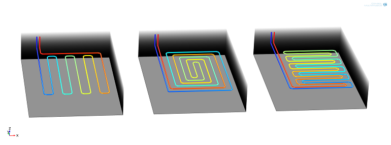
The number of possibilities of how the heat collector pipes can be arranged in the subsurface is endless. Here, we will have a look at three randomly chosen patterns. Let’s call them snake, snail, and meander designs. The heat collector is embedded in the subsurface with typical thermal properties that you could find in the uppermost soil layer in your garden. The subsurface temperature distribution corresponds to that of the temperature in Germany during the month of January.

Three different layer designs for a geothermal heat collector system: 1) snake, 2) snail, and 3) meander design.
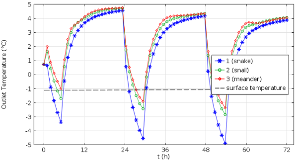
The COMSOL Multiphysics feature, geometry subsequence, allows us to create all of the three different pipe geometries within the same model. It also allows us to perform a parametric study that solves for each particular sub-geometry. We can compare the different designs by having a look at the resulting outlet temperature as a function of time.

Comparison of the outflow temperatures of the three collector designs.
The three collectors each show a different thermal behavior. This is due to the varying distances between the pipes, their different lengths, and thereby the surface available for heat transfer. Even though the freezing point of the water-glycol mixture inside the pipes is at about -13°C, the outflow temperature is — for environmental reasons — legally limited to stay above -5°C in Germany.
The snake design tends to go below this point only after a few days and would, thus, not be the preferred design here. However, a geothermal engineer could now proceed to optimize a design (modify the pipe length, pipe diameter, or the covered area to reach a maximum outlet temperature, for example.) One could, of course, also easily perform long time runs to study the impact of seasonal temperature variations or even use the pipes for cooling purposes in the summer.
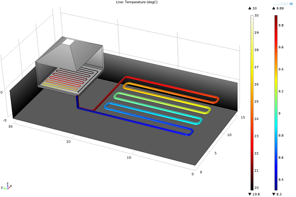
Once the optimal design of the geothermal heat collector in your garden is found, why not go on and model the modern underfloor heating system in the house? The procedure is straight-forward. There is only a change of sign because heat is injected here.

Combined model of a garden heat collector together with an underfloor house heating system. The collector extracts heat from the subsurface at 6 kW, while the house heating system injects heat into the floor of the house at 30°C.
Other Posts in This Series
- Modeling Geothermal Processes with COMSOL Software
- Coupling Heat Transfer with Subsurface Porous Media Flow
Further Reading
- Read about designing heat exchangers
- Explore the Pipe Flow Module


Comments (2)
BOUKLI HACENE Mohammed El Amine
September 10, 2018Dear
I have a COMSOL version, 5.0 (32 bits), I need to download the application file for the Heat Recovery System for Geothermal Heat Pump https://www.comsol.com/model/heat-recovery-system-for-a-geothermal-heat-pump-18529
I fond only the application for COMSOL 5.2a, 5.3, and 5.3a, I have the 5.0 COMSOL version
Thank you for the help
Phillip
September 11, 2018 COMSOL EmployeeDear Mohammed,
please send your request to our technical support support@comsol.com to receive a 5.0 version (if existent).
Best regards,
Phillip