
Gears are used in a variety of applications, such as clocks, industrial machinery, music boxes, bicycles, and automobiles. A gearbox is a major source of vibration and noise irrespective of how it is used. The most effective approach to reduce the noise radiation from a gearbox is to perform a vibroacoustic analysis to improve the design. Let’s see how the COMSOL Multiphysics® software can be used to help build quieter transmission systems.
Noise, Vibration, and Harshness (NVH) Analysis of a Gearbox
A gearbox assembly generally consists of gears, shafts, bearings, and housing. When operated, a gearbox radiates noise in its surroundings for two main reasons:
- Transmission of undesired lateral and axial forces on the bearings and housing while transmitting power from one shaft to another
- Flexibility in the different parts of the gearbox, such as the gear mesh, bearings, and housing
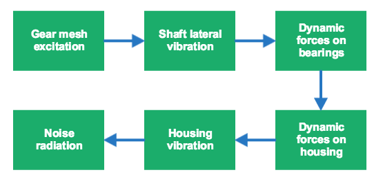
Out of all of the components in a gearbox, the primary source of vibration or noise is the gear mesh. A typical path followed by the structural vibration, seen as the noise radiation in the surrounding area, can be illustrated like this:
Gear Whine and Rattle
The noise generated due to gear meshing can be classified into two types: gear whine and gear rattle.
Gear whine is one of the most common types of noise in a gearbox, especially when it runs under a loaded condition. Gear whine is caused by the vibration generated in a gear because of the presence of transmission error in the meshing as well as the varying mesh stiffness. This type of noise occurs at the meshing frequency and typically ranges from 50 to 90 dB SPL when measured at a distance of 1 m.
Gear rattle is observed mostly when a gearbox is running under an unloaded condition. Typical examples are diesel engine vehicles such as buses and trucks at idle speed. A gear rattle is an impact-induced noise caused by the unloaded gear pairs of the gearbox. Backlash, required for lubrication purposes, is one of the gear parameters that directly impact the gear rattle noise. If possible, simply adjusting the amount of backlash can reduce gear rattle.
Transmission Error
We know that transmission error is the main cause of gear whine, but what exactly is it? When two rigid gears have a perfect involute profile, the rotation of the output gear is a function of the input rotation and the gear ratio. A constant rotation of the input shaft results in a constant rotation of the output shaft. There can be various unintended and intended reasons for modifying the gear tooth profile, such as gear runouts, misalignment, tooth tip, and root relief. These geometrical errors or modifications can introduce an error in the rotation of the output gear, known as the transmission error (TE). Under dynamic loading, the gear tooth deflection also adds to the transmission error. The combined error is known as the dynamic transmission error (DTE).
Modeling Gearbox Vibration and Noise in COMSOL Multiphysics®
Reducing gear whine or rattle to an acceptable level is a big challenge, especially for modern complex gearboxes, which consist of many gears meshing simultaneously. By accurately simulating these complex behaviors, we can design a quieter gearbox. COMSOL Multiphysics gives designers the ability to accurately identify problems and propose realistic solutions within the allowable design constraints. With such a tool, we can optimize existing designs to reduce noise problems and gain insight into new designs earlier in the process, well before the production stage.
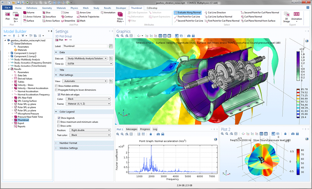
A gearbox model in the COMSOL Desktop®.
Let’s consider a five-speed synchromesh gearbox of a manual-transmission vehicle in order to study the vibration and radiation of gear whine noise to the surrounding area. The gearbox is in a car and used to transfer power from the engine to the wheels.
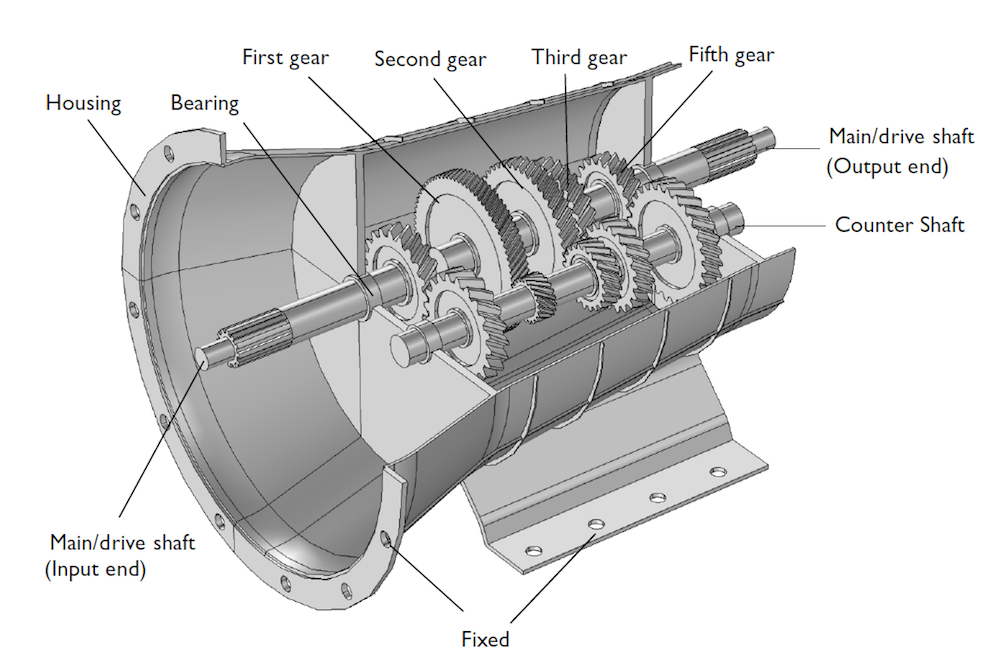
Geometry of a five-speed synchromesh gearbox of a manual transmission vehicle.
In order to numerically simulate the entire phenomenon of gearbox vibration and noise, we perform two analyses:
- Multibody analysis
- Acoustic analysis
In the multibody analysis, we compute the dynamics of the gears and housing vibrations, performed at the specified engine speed and output torque in the time domain. For the acoustic analysis, we compute the sound pressure levels outside the gearbox for a range of frequencies using the normal acceleration of the housing as a source of noise.
Analyzing Vibration in a Gearbox
First, we look into the gear arrangement in the synchromesh gearbox. Here, helical gears are used to transfer the power from the input end of the drive shaft to the counter shaft and further from the counter shaft to the output end of the drive shaft.
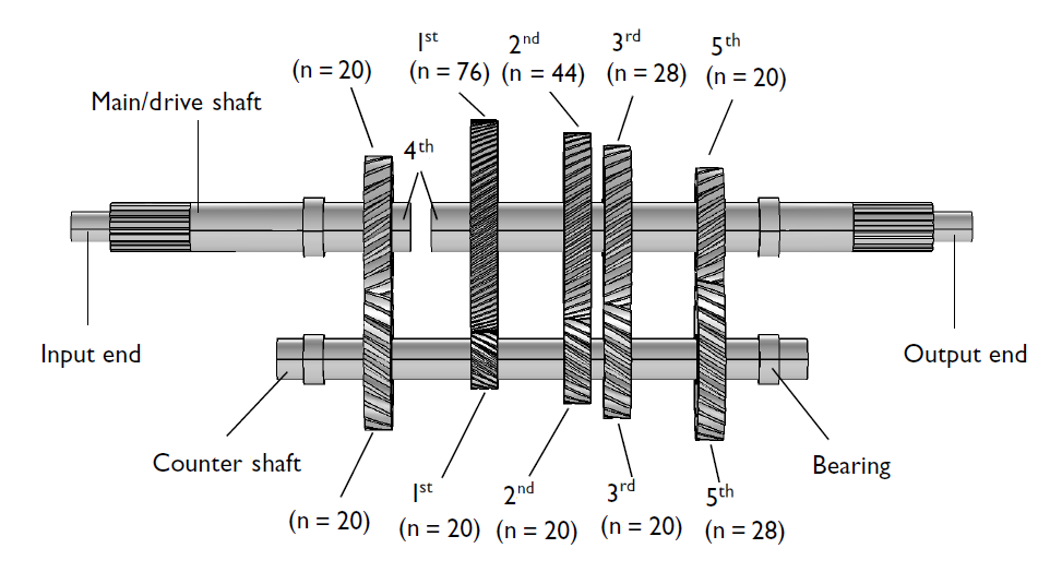
The gear arrangement in the five-speed synchromesh gearbox, excluding the synchronizing rings that connect the gears with the main shaft.
The gears used in the model have the following properties:
| Property | Value |
|---|---|
| Pressure angle | 25 [deg] |
| Helix angle | 30 [deg] |
| Gear mesh stiffness | 1e8 [N/m] |
| Contact ratio | 1.25 |
All of the gears on the counter shaft are fixed to the shaft, whereas the gears on the drive shaft can rotate freely. Only one gear at a time is fixed on the shaft. In real life, this is achieved with the help of synchronizing rings. In the model, hinge joints with an activation condition are used to conditionally engage or disengage gears with the drive shaft.
Looking at the shafts, they are assumed rigid and rested on the housing through hinge joints, whereas the housing is assumed flexible, further mounted on the ground, and connected to the engine at one of its ends. The driving conditions considered for the simulation in terms of engine speed, load torque, and the engaged gear are as follows:
| Input | Value |
|---|---|
| Engine speed | 5000 [rpm] |
| Load torque | 1000 [N-m] |
| Engaged gear | 5 |
With these settings, it is possible to run a multibody analysis and compute the housing vibrations as shown in this animation:
The von Mises stress distribution in the housing together with the speed of different gears.
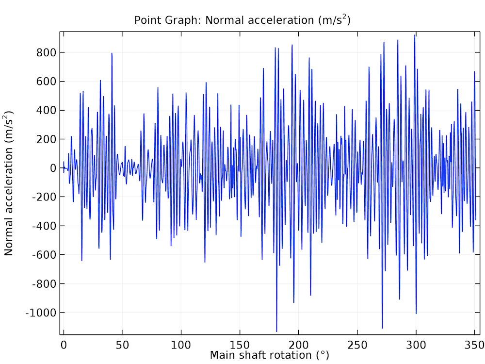
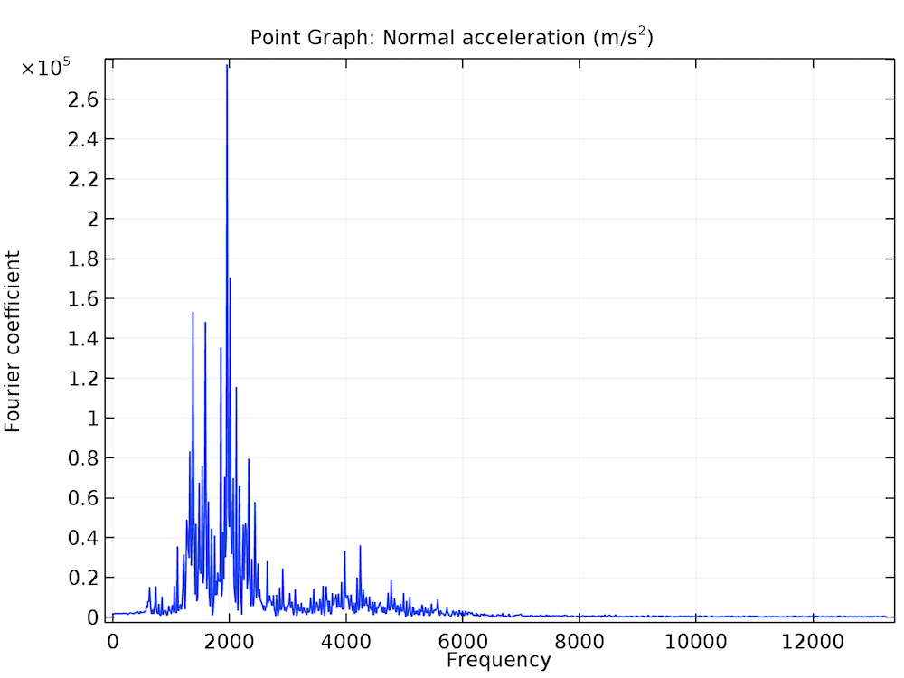
In order to have a better understanding of the variation of normal acceleration as a function of time, we can choose any point on the gearbox housing. The time history of the normal acceleration at that point is shown below. Let’s transform this result to the frequency domain using the FFT solver. In this way, we can find the frequency content of the vibration. It is clear from the frequency response plot that the normal acceleration of the housing contains more than one dominant frequency. The frequency band in which the housing vibration is dominant is 1000–3000 Hz.
Time history and frequency spectrum of the normal acceleration at one of the points on the gearbox housing.
Performing an Analysis of the Gearbox Noise
Once we have simulated the vibrations in a gearbox, let’s see how to model the noise radiation in COMSOL Multiphysics. To begin, we create an air domain outside the gearbox to simulate the noise radiation in the surrounding.
In order to couple multibody dynamics and acoustics, we assume a one-way coupling, as the exterior fluid is air. This implies that the vibrations from the gearbox housing affect the surrounding fluid, whereas the feedback from the acoustic waves to the structure is neglected. It is a good assumption that the problem is one-way coupled.
The acoustic analysis is performed for a range of frequencies. As the multibody analysis is solved in the time domain, the FFT solver is used to convert the housing accelerations from the time domain to the frequency domain.
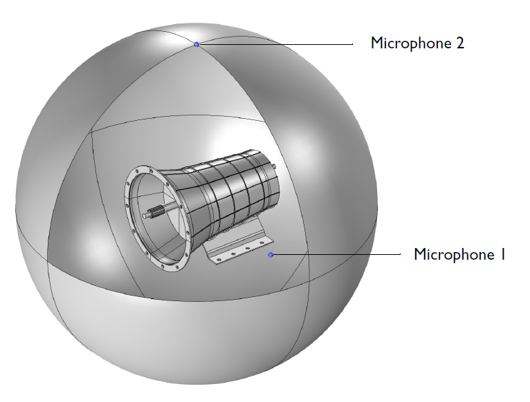
The air domain enclosing the gearbox for acoustic analysis. The two microphones placed to measure noise levels are shown.
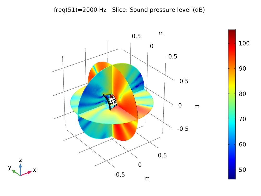
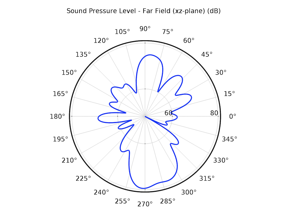
As a source of noise, the normal acceleration of the gearbox housing is applied on the interior boundaries of the acoustics domain. In order to avoid any reflections from the exterior boundaries of the surrounding domain, we apply a spherical wave radiation condition. With these settings, we can solve for the acoustic analysis and look at the sound pressure level in the near field as well as on the surface of the gearbox housing at different frequencies. For a better understanding of the directivity of the noise radiation, we can create far-field plots in different planes at different frequencies.
The sound pressure level in the near field (left) and at the surface of the gearbox (right).
The far-field sound pressure level at a distance of 1 m in the xy-plane (left) and xz-plane (right).
After visualizing the sound pressure level in the outside field, it is interesting to find out the variation of sound pressure with frequency at a particular location. For this purpose, two microphones are placed in specific locations.
| Microphone | Placement | Position |
|---|---|---|
| 1 | Side of the gearbox | (0, -0.5 m, 0) |
| 2 | Top of the gearbox | (0, 0, 0.75 m) |
These microphone locations are defined in the Parameters node in the results and can be changed without updating the solution every time.
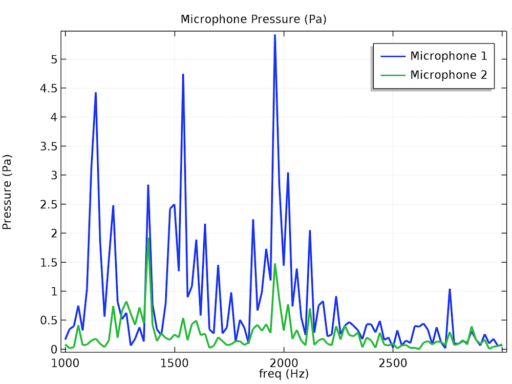
The frequency spectrum of the pressure magnitude at the two microphone locations.
The pressure response plot at the microphone locations gives a good idea of the frequency content present in the noise. However, wouldn’t it be nice if we could actually listen to the noise recorded at the microphone, just like in a physical experiment? This is possible by writing Java® code in a method using the magnitude and phase information of the pressure as a function of frequency.
Let’s listen to the sound files corresponding to the noise received at the two microphones…
We have already looked at the acoustics results for various frequencies. It would also be nice to see them in the time domain. Let’s transform the results from the frequency domain to the time domain using the FFT solver so that we can visualize the transient wave propagation in the surrounding area of the gearbox.
Animation showing the transient acoustic pressure wave propagation in the surrounding area of the gearbox.
Designing a Quieter Gearbox with Simulation
The above approach describes a technique to couple multibody analysis and acoustics simulation in order to accurately compute the noise radiation from a gearbox. This technique can be used early in the design process to improve the gearbox in such a way that the noise radiation is minimal in the range of operating speeds of the gearbox. Additionally, methods — new functionality as of version 5.3 of the COMSOL Multiphysics® software — enable us to actually hear the noise generated by the gearbox — making the simulation one step closer to a physical experiment.
Additional Multibody Dynamics and Gear Modeling Resources
- Learn how to evaluate gear mesh stiffness
- Get started simulating gears with these tutorial models:






Comments (7)
Pravin Patil
December 11, 2019Hey Pawan, I hope you are doing excellent. I am working in JohnDeere in Drivetrain NVH Team. I went through your blog about the stuff which you published. I do have few questions. I am in US for a while so would like to understand the capability about your tool. Can you schedule meeting to discuss. I am working in USA CST time zone. My preferred time would be morning 7 AM to 4PM. I am waiting for your reply.
Thank you,
Pravin
Pawan Soami
December 12, 2019 COMSOL EmployeeDear Pravin,
Thanks for showing your interest in the area of modeling gearbox NVH. We would certainly be happy to discuss your queries and explain the capabilities of our tool. You can send an email to support@comsol.com with your contact details for further discussion.
Best regards,
Pawan Soami
Ali Kazemi
January 14, 2021Hi Pawan Soami,
Thank you for your explanation and this great job.
I am trying to model birds trachea for my postdoc project and somehow I want to lesson to final produced sound.
I saw that you mentioned we can hear sound with some Java code. Could you please help me in this case? How I can access this code and how is working?
Thank you in advance.
Kazemi
Pawan Soami
January 19, 2021 COMSOL EmployeeDear Ali,
Thank you for reading and showing your interest.
You can find the Java code and its working in the gearbox_vibration_noise model available the Application Library. Here is the link of the model:
https://www.comsol.com/model/modeling-vibration-and-noise-in-a-gearbox-47841
The model link is also given towards the end of the blog. You can open this model and switch to the Application Builder to see the java code.
Best regards,
Pawan Soami
Raghunath Thiagarajan
March 24, 2021Dear Pawan,
Hope you are doing well. I am currently working on Frictional Heat generation in gears during motion. However, being a beginner, I could not couple the Heat Transfer and Multibody Dynamics nodes (under the multi – physics) without getting errors. I could not find a Comsol tutorial for this specific problem. Can you please give me some insights into this? What are the governing equations and boundary conditions that I should apply? What are some other important things that I should keep in mind?
Thanking you!
With regards,
Raghunath.
Pawan Soami
March 25, 2021 COMSOL EmployeeDear Raghunath,
I am doing well and hope you are doing good too! When you are modeling frictional heat generation in gears during motion, there is a built-in variable for Energy dissipation rate due to friction (mbd.grp1.Qf) defined by Friction subnode of the Gear Pair node. This defines the total power loss due to friction between two gears. This variable should be coupled with heat transfer physics in case you want to see the rise in temperature and its distribution on gears.
Note that the Qf variable is a total power so you need to distribute it on the contacting surfaces of gear pair. In general the time scale of gear rotation is much smaller (2-3 orders of magnitude) compared to hear transfer physics, so it is sufficient to distribute it on all the teeth of both gears rather than finding the instantaneous contact areas.
If you face any issues in implementing the same, please feel free to reach out to us on support@comsol.com.
Best regards,
Pawan Soami
Harjot International
February 9, 2024Thank you for sharing valuable tips on how to model gearbox vibration and noise. Through accurate simulations, designers can solve problems and propose practical solutions. It helps optimize designs for reduced noise and provides insights into new designs earlier in the process.
https://www.rollingmachinery.net/reduction-gear-box.html