
The lid-driven cavity is a popular problem within the field of computational fluid dynamics (CFD) for validating computational methods. While the boundary conditions are relatively simple, the flow features created are quite interesting and complex. Here, we demonstrate how to define this benchmark problem in the COMSOL Multiphysics® software. We also showcase techniques like mapped meshing and nonlinearity ramping, which can be applied to a wide variety of CFD models.
Modeling a Lid-Driven Cavity in COMSOL Multiphysics®
The lid-driven cavity consists of a square cavity filled with fluid. At the top boundary, a tangential velocity is applied to drive the fluid flow in the cavity. The remaining three walls are defined as no-slip conditions; that is, the velocity is 0.
For benchmarking purposes, we want to solve something general that can easily be implemented in different tools. How can we compare different computational methods using the most generic formulation of this problem? One way is to nondimensionalize the equations, which means that the problem will not depend on specific materials, length scales, or operating conditions. In the case of fluid flow in a lid-driven cavity, we can solve the nondimensional Navier-Stokes equations.
The incompressible, stationary Navier-Stokes equations with no body forces take the following form:
By nondimensionalizing the velocity (\textbf u^* = \frac{\textbf u}{U} ), pressure (p^* = \frac{p}{\rho U^2} ), and length scale (\textbf r^* = \frac{\textbf r}{L} , \nabla^*=L\nabla ), we can reformulate this equation as:
The Reynolds number is defined as Re = \frac{\rho UL}{\mu}. This nondimensional number describes the relative importance of the inertial forces to the viscous forces in the flow, as described in this blog post.
By comparing the forms of these two equations, we can determine which parameters need to be entered into the COMSOL Multiphysics model in order to solve the nondimensionalized equations. Specifically, we see that the coefficient in front of the inertial term (\textbf u^* \cdot \nabla^* )\textbf u^* is 1, so we apply a density of 1 in the material properties. For the viscous term \nabla^{*2} \textbf u, we see that the coefficient is \frac{1}{Re}, so this is entered as the viscosity.
Applying Nonlinearity Ramping
As the Reynolds number increases, the viscous term becomes less significant in the equation compared to the inertial term. Since the viscous term in the equation is linear and the inertial term is nonlinear, increasing the Reynolds number leads to the problem becoming more nonlinear. When solving nonlinear problems, we often want to apply nonlinearity ramping to provide good initial conditions for the solver. Nonlinearity ramping is discussed in detail in the following blog posts:
- Viscosity Ramping Improves the Convergence of CFD Models
- Nonlinearity Ramping for Improving Convergence of Nonlinear Problems
In this model, we perform an auxiliary sweep in the study over multiple Reynolds numbers. This sweep serves two purposes:
- Comparing the solutions for different Reynolds numbers to the results in the literature
- Demonstrating how to perform nonlinearity ramping to help the solver
In this case, the problem does not require nonlinearity ramping in order to converge. However, for highly nonlinear problems, this is an important technique to consider when improving the convergence.
Setting Up the Boundary Conditions and Constraints
In terms of boundary conditions, the top wall moves at a velocity of U = 1 in the x direction. The other three walls are applied as no-slip conditions (U = 0).
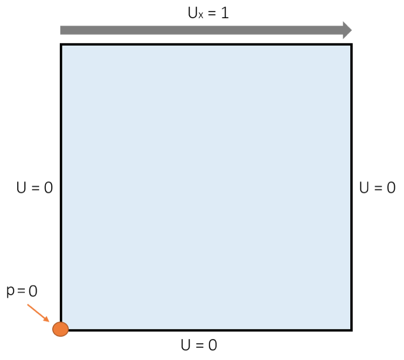
The boundary conditions for the lid-driven cavity model.
While these boundary conditions fully describe the physical problem we want to solve, there is one other essential condition that we need to apply to the closed cavity: a pressure point constraint. In a closed system at steady state, there are no inlets or outlets in which the pressure level is defined. Without a reference level for the pressure, the Navier-Stokes equations have infinite solutions to the steady-state problem, since they only solve with respect to the gradient in pressure. Thus, the pressure point constraint provides information about what the absolute pressure levels should be in the flow. When we apply a pressure point constraint of p = 0, it corresponds to an absolute pressure of 1 atm, as explained in this blog post on how to assign fluid pressure.
It is important to apply a pressure point constraint far away from the interesting behavior in the flow any time we solve for steady flow in a closed cavity — whether it is a mixed tank reactor or a natural convection problem. A couple of example models that use pressure point constraints are the Free Convection in a Water Glass and Modular Mixer tutorials.
Using Mapped Meshing to Discretize the Domain
Now that we have defined the boundary conditions, we can think about how we want to discretize the domain. The lid-driven cavity provides a perfect example of how mapped meshing can be applied to efficiently and effectively discretize four-sided geometries. Mapped meshing discretizes the domain using rectangular elements. These elements don’t need to be uniformly spaced. In fact, we can use Distribution subnodes to the Mapped node in the mesh sequence to define how the elements are spaced along the edges. In the lid-driven cavity, we want to stack more elements near the no-slip walls, where the gradients in the flow are higher, so we apply symmetric distributions along all of the edges.
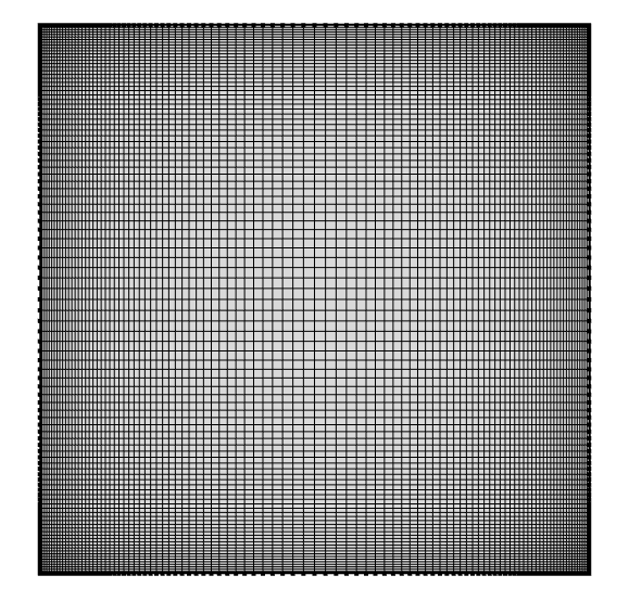
The mapped meshing of the lid-driven cavity model.
While we are applying mapped meshing to a square in this case, the technique can be applied to any four-sided geometry. Irregular geometries can even be subdivided into four-sided entities so that mapped meshing can be applied. In some cases, mapped meshing can be computationally more efficient than free triangular meshing and it gives us more control over the element spacing. For examples of using mapped meshing, check out the Nonisothermal Turbulent Flow over a Flat Plate and Dissociation in a Tubular Reactor tutorials.
Comparing the CFD Simulation Results to Existing Literature
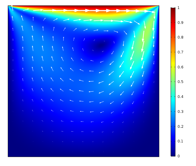
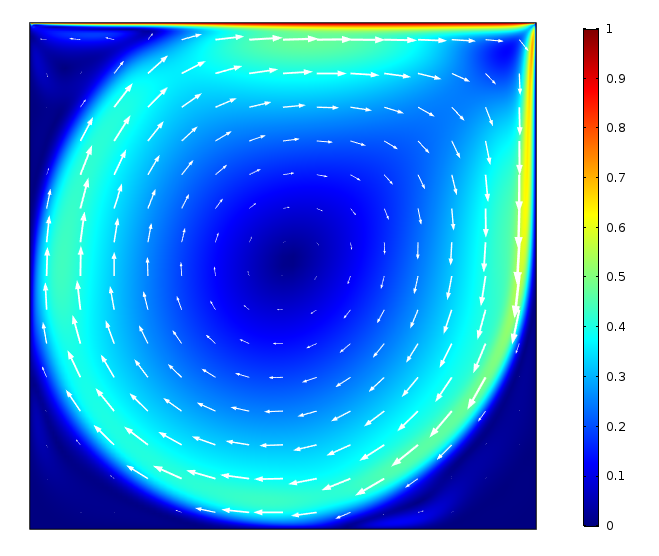
Now, let’s take a look at the results. First, we check the magnitude of the velocity in the cavity, plotted with the rainbow color scale, and the direction of the flow, indicated with the vector plot. We see that the velocity approaches U = 1 at the top of the cavity, where the fluid flow is being driven by the moving wall. The fluid is pushed into the wall on the right, where it flows downward before moving back up the left side of the cavity. This motion creates a large vortex in the center of the cavity. We can see that for a lower Reynolds number of 100 (figure on the left), the velocities in the center of the cavity are lower due to the dissipation of the energy through the large viscous term. As the Reynolds number increases to 10,000 (figure on the right), we see that the velocities are higher in the cavity and the vortex extends more prominently into the bottom of the cavity.
The magnitude of the velocity and the direction of the flow in the cavity for Reynolds numbers of 100 (left) and 10,000 (right).
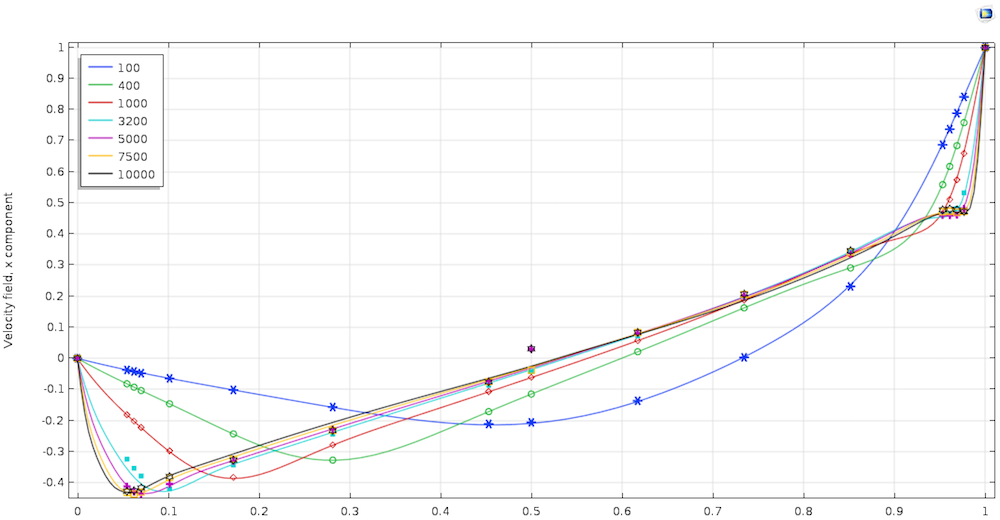
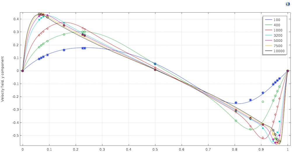
The lid-driven cavity is a benchmark problem, so we want to compare it to existing literature (Ref. 1). To do so, let’s take a look at the velocities along the centerlines of the cavity. In the left image below, we see the x-component of the velocity (u) plotted along the vertical centerline, while the right image below plots the y-component of the velocity (v) along the horizontal centerline. We see that the simulation results closely match the results from the literature for the entire range of Reynolds numbers.
Comparison of the results from the simulation and literature for the x– (left) and y-components (right) of the velocity for various Reynolds numbers.
The velocity plot above shows that a large vortex is formed in the center of the cavity, but what about the flow behavior in the corners? We use streamlines to visualize the flow structures in all parts of the cavity. Because there is no inlet in this simulation, we set the Streamline Positioning to Uniform density (instead of On selected boundaries).
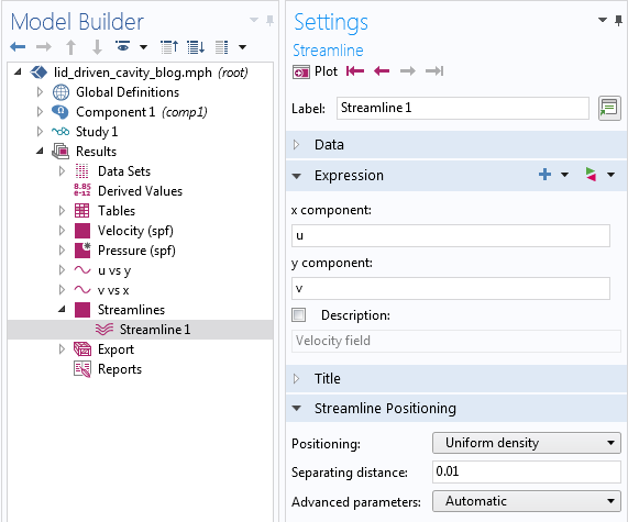
Settings window showing the Streamline Positioning set to Uniform density.
We can see that for lower Reynolds numbers, the flow separates near the bottom left and right corners and two vortices are formed. As the Reynolds number increases, there is more inertia in the flow, causing it to separate earlier along the wall and create larger corner vortices. Increasing the Reynolds number further, a third vortex forms in the top left corner. For the highest Reynolds number (10,000), two vortices are present in the bottom corners in addition to the one in the top left corner.
The flow in the cavity for various Reynolds numbers.
Concluding Thoughts on the Lid-Driven Cavity Problem
Here, we have showed how to define a classic CFD problem, the lid-driven cavity. An auxiliary sweep has enabled us to solve for multiple Reynolds numbers while improving the convergence of the simulation. We have also demonstrated how you can leverage mapped meshing to efficiently discretize a four-sided geometry and better resolve the high gradients in the flow near the walls. In addition, we have compared the results to existing literature and found that they closely match.
Next Steps
To try this example yourself, click the button below to head to the Application Gallery.
Reference
- U. Ghia, K.N. Ghia, and C.T. Shin, “High-Re Solutions for Incompressible Flow Using the Navier-Stokes Equations and a Multigrid Method,” Journal of Computational Physics, vol. 48, pp. 387–411, 1982.




Comments (7)
John Neumann
May 8, 2018Hi Angela,
Great post- I think I have a better understanding/feel of the meaning of the Reynolds number now. Since turbulence isn’t mentioned, does that mean these simulations were done assuming laminar flow (or if the turbulence model was used, which one?)? What meaning should we attach to the results for Re> 2000 or so, where turbulent flow behavior is expected to start, if the simulations don’t include a turbulence model? Thanks
Leon Kamp
May 9, 2018Hi Angela,
Would it be possible to get the Comsol model of the lid-driven cavity problem? Thanks.
Leon Kamp
Dmitrii Lazarev
May 9, 2018John, the critical Reynolds number depends on flow conditions. The critical value of about 2000 is for flow in tubes, not for flow in closed cavities.
John Neumann
May 9, 2018Thanks Dmitrii, I didn’t know that. That’s useful for me because I am interested in modeling flow in a cavity, in particular gas coming through small inlet tubes into a much larger chamber. If I calculate Re with the diameter of the tube and the gas speed, I get a small Re. Likewise, if I calculate Re using typical gas speeds in the chamber along with the size of the chamber, again I get small Re (because the speed goes way down, even though the length scale is much larger). What concerns me is should I use the worst case, i.e. the large speed in the inlet tube combined with the large length scale of the chamber, to calculate Re? Then I definitely get Re in the thousands. My instinct says that if there is going to be turbulence, it will be where the gas exits the inlet tube, where the speed is high but there suddenly is less viscous force because of the distance from all walls. Does this sound correct?
James D Freels
May 10, 2018The critical assumption in the model is laminar flow and also dimensionless formulation of the equations. One can turn on the turbulence model if you want just to see the difference. It has been my experience that the laminar version of the model will go unstable at about the same place where turbulence is needed to keep it stable.
This model is apparently using equation-based modeling and is probably not in the application library. I was able to reproduce these results by modifying the thermal-driven cavity application that is in the library. By manually specifying the fluid properties and changing the length scale, you can get the Reynolds number to be equivalent to the inverse of the dynamic viscosity. It was interesting to experiment with the discretization level and solver settings. I was able to get a stable solution up to about Reynolds number = 50,000, but at 100,000 it went unstable. This was using a P2-P2 discretization and the normal physics-based mesh. You get a few more recirculation zones when you do this.
Thank you for posting this Angela. This is a very interesting, and classical CFD benchmark.
Angela Straccia
May 15, 2018 COMSOL EmployeeThank you for your comments. To address them:
John, as Dmitrii mentioned, the critical Reynolds number for transition will depend on the type of flow. For instance, for flow along a flat plate, the transition occurs around 5×10^5, which is quite different than the transition regime in a pipe flow (~2000). This model solves for the same Reynolds numbers as the paper published by Ghia et al, and convergence is achieved using Laminar Flow physics for the entire range (100-10,000). In terms of determining the flow regime for your specific problem, we recommend contacting our support team directly: support@comsol.com
Jim, thanks for your positive feedback! This model was created using the Laminar Flow interface with the default discretization of P1+P1. In order to solve in dimensionless form, the global unit system is set to “None” and the density and viscosity are set as the coefficients to the inertial (1) and viscous (1/Re) terms in the non-dimensional Navier-Stokes equations (see blog).
Angela Straccia
May 25, 2018 COMSOL EmployeeHi Leon, thanks for your interest in the model. You will find the model as well as the associated documentation by clicking the “Get the Tutorial Model” button at the bottom of the blog.