
The Port boundary condition in the RF Module, an add-on to the COMSOL Multiphysics® software, can be used to launch and absorb electromagnetic energy. We explain how to set up a circular waveguide port and review the analytical solution that defines the port mode field. We also analyze a polarized circular port for power transmission with respect to port orientation, and then extend the model to include higher-order modes.
Circular Port Reference Axis for Describing Degenerate Modes
To simulate wave propagation in a circular waveguide, we need to set up the excitation and termination via boundary conditions that describe the mode field. However, circular ports exhibit degeneracy, which yields uncertainty in the orientation of the mode field. Let’s begin our discussion on how we can use the Circular Port Reference Axis subfeature to suppress angular degeneracy in a circular waveguide port.
The dominant TE11 mode exhibits degeneracy. To fix the orientation of the mode field, we use the Circular Port Reference Axis subfeature.
First, we run a Mode Analysis study to find the resonant modes on a simple circle in 2D, which represents our port boundary. Among the modes returned by default, some are simple rotations of the exact same TE11 mode shape about the origin. So, how can we determine which solution is correct? All of them are equally accurate solutions to the equations describing the transverse field components of a circular waveguide (Ref. 1):
E_{\rho}=\frac{-j\omega\mu m}{k_{c}^{2}\rho}(A \ cos \ m\phi-B \ sin \ m\phi) \ J_{m}(k_{c}\rho) \ e^{-j\beta z}E_{\phi}=\frac{j\omega\mu}{k_{c}}(A \ sin \ m\phi+B \ cos \ m\phi) \ J’_{m}(k_{c}\rho) \ e^{-j\beta z}
H_{\rho}=\frac{-j\beta}{k_{c}}(A \ sin \ m\phi+B \ cos \ m\phi) \ J’_{m}(k_{c}\rho) \ e^{-j\beta z}H_{\phi}=\frac{-j\beta m}{k_{c}^{2}\rho}(A \ cos \ m\phi-B \ sin \ m\phi) \ J_{m}(k_{c}\rho) \ e^{-j\beta z}
Here, m represents the value of the first mode index, Jm is the Bessel function of the first kind, and J’m is the derivative of the Bessel function. The argument is the cutoff wavenumber kc=χ’mn/a.

Two points on the port circumference are used to define the orientation of the fields on the boundary. We can imagine a line connecting the two points in each selection to form the reference axis.
The seemingly identical modes arise because circular ports are degenerate. This means that an infinite number of rotations of a given mode field can exist on the same boundary, which can be problematic for describing the orientation of port mode fields with respect to one another. We therefore define a Circular Port Reference Axis, which is available as a subfeature to the Port node. This feature allows us to select two vertices on the port circumference that define the orientation of fields on the port boundary. The mode field is then defined with respect to this reference axis, and any uncertainty in its orientation is resolved. We may now extend our study of circular ports to 3D.
TE11 mode propagating through a circular waveguide. The animation of the contour plot shows the z-component of the E field, created with the full dynamic data extension sequence type. The arrow plot describes the electric mode field on the port boundary.
Modeling a Polarized Circular Waveguide
Let’s consider the Polarized Circular Ports model, available in the RF Application Gallery. This tutorial demonstrates how to excite and terminate a port with degenerate port modes. The structure under study is a straight, circular waveguide surrounded by perfectly conducting walls.
As with any COMSOL Multiphysics model, we start by building the geometry, assigning materials, and then setting up the physics. Our structure here is a simple cylinder filled with air. We model the metallic boundaries on the exterior using the Perfect Electric Conductor boundary condition. Since this condition assumes a lossless conductor, there is no need to assign a material to these boundaries. Next, we add a Port boundary condition and select the circular boundary at one end of the waveguide.
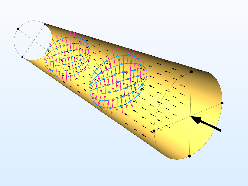
The outer walls of the waveguide are modeled as Perfect Electric Conductor boundaries. Streamlines of the electric fields are shown in red, and magnetic fields in blue. Arrow plots (black) show the direction of power flow from the excitation port to listener ports. Solid lines represent the reference axis for ports 1 and 2 on the near end, and ports 3 and 4 on the far end.
In the Port 1 settings, we start by setting the geometry type to Circular. When using a circular port, the mode type (TE or TM) and mode number must be specified. TE and TM stand for transverse electric and transverse magnetic, respectively; both of these mode types are supported by circular ports. Circular mode numbers are described by two indices, m and n, which are used in the transverse magnetic and electric field equations shown above.
We are interested in the dominant TE11 mode. Therefore, in the Port 1 settings, we set the mode type to TE and mode number to 11. We select two opposite vertices on the port circumference in the Circular Port Reference Axis subfeature. Now, the important question becomes: How can we terminate this mode at the other end of the waveguide?
Any incident field can be completely terminated by two mutually orthogonal ports with the same mode field shape. We can verify this by expanding the Polarized Circular Waveguide model to study transmittance when the listener ports’ reference axes are rotated with respect to that of the excitation port. In this model, we set up a total of four ports, only one of which is an excitation port (Port 1). Together, mutually orthogonal ports 1 and 2 receive all of the reflected energy, while mutually orthogonal ports 3 and 4 receive all of the transmitted energy.
We run a Parametric Sweep where the reference axes of ports 3 and 4 are rotated together by an angle theta about the origin. This rotation angle is plotted on the x-axis in the plot below. S-parameters are available as built-in expressions, ready for evaluation in postprocessing. The power ratio transmitted to ports 3 and 4 can be evaluated as the magnitude squared of S31 and S41, respectively. We used this relation to evaluate the transmittance at each angle spanned in the plot below.
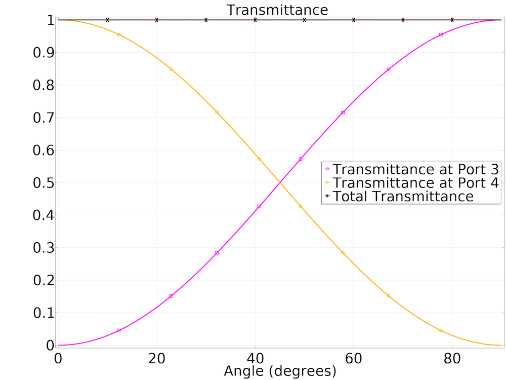
At any angle, the transmittance values sum to one, indicating nearly zero reflection, and therefore ideal termination. The reference axis of the first receiving port can be chosen freely as long as the reference axis of the second receiving port is a 90-degree rotation of the first about the waveguide axis.
An Important Consideration: Cutoff Frequency
Anytime we wish to excite a waveguide or port, it is important to consider the cutoff frequency of the structure — that is, the lowest frequency for which a particular mode can propagate. This is true not only for the dominant mode but also higher-order modes. Rectangular, circular, and coaxial ports each have analytical expressions for cutoff frequency. This value is dependent on the size of the structure, the medium inside it, as well as the mode number. Below are the equations for cutoff frequency for both TE and TM modes in a circular waveguide:
f_c=\frac{\chi’_{mn}}{2\pi a \sqrt{\mu\epsilon}} for TE modes
f_c=\frac{\chi_{mn}}{2\pi a \sqrt{\mu\epsilon}} for TM modes
Here, a is the radius, μ is the permeability, and ε is the permittivity.
The values of χ’mn are given by the zeros of the derivative of the Bessel function Jm(x); these are needed to determine cutoffs for TE modes. The values of χmn are given by the zeros of the Bessel function; these are needed to determine cutoffs for TM modes. Luckily, the zeros of the Bessel function and its first derivative are well known, and some of them are listed here.
You may notice that the values in the m = 0 column of the χ’mn table are identical to the values in the m = 1 column of the χmn table. Therefore, the TE0n and TM1n modes have identical cutoff frequencies and are referred to as degenerate modes.
| Mode Index | m = 0 | m = 1 | m = 2 | m = 3 | m = 4 | m = 5 |
|---|---|---|---|---|---|---|
| n = 1 | 2.4049 | 3.8318 | 5.1357 | 6.3802 | 7.5884 | 8.7715 |
| n = 2 | 5.5201 | 7.0156 | 8.4173 | 9.7610 | 11.0647 | 12.3386 |
| n = 3 | 8.6537 | 10.1735 | 11.6199 | 13.0152 | 14.3726 | 15.7002 |
Zeroes χmn of the first kind Bessel function Jm(x) used in TM mode. (Ref. 2)
| Mode Index | m = 0 | m = 1 | m = 2 | m = 3 | m = 4 | m = 5 |
|---|---|---|---|---|---|---|
| n = 1 | 3.8318 | 1.8412 | 3.0542 | 4.2012 | 5.3175 | 6.4155 |
| n = 2 | 7.0156 | 5.3315 | 6.7062 | 8.0153 | 9.2824 | 10.5199 |
| n = 3 | 10.1735 | 8.5363 | 9.9695 | 11.3459 | 12.6819 | 13.9872 |
Zeroes χ’mn of the derivative of the first kind Bessel function J’m(x) used in TE mode. (Ref. 2)
The number of modes that can exist in a given waveguide increases with frequency. Below, we show the first 24 modes of a circular port in the order of increasing cutoff frequency.
 TE11 |
 TM01 |
 TE21 |
 TM11 |
 TE01 |
 TE31 |
 TM21 |
 TE41 |
 TE12 |
 TM02 |
 TM31 |
 TE51 |
 TE22 |
 TE02 |
 TM12 |
 TE61 |
 TM41 |
 TE32 |
 TM22 |
 TE13 |
 TE71 |
 TM03 |
 TM51 |
 TE42 |
The first 24 modes of a circular port are shown. For TE modes, a surface plot of the electric field norm and arrow plot of the magnetic fields are displayed. For TM modes, a surface plot of the magnetic field norm and arrow plot of the electric fields are displayed.
Automate the Data Collection Process Using Methods
To produce the figure above, we used a powerful tool called methods to accelerate the modeling workflow. A method contains a series of commands. When called, these tasks are run automatically within the software. Here, we use a method to automate and expedite the process of producing the field distributions for the first 24 modes of a circular port. The method performs the following actions sequentially:
- Calculate the cutoff frequency for a given mode
- Enter the mode numbers in the Port node settings
- Run the model at a frequency value just above the cutoff and store the solution at the port boundary
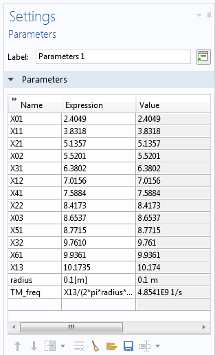
The method loops through this process for each mode, using its respective χmn/χ’mn constant (the values of which are entered in the Parameters node).
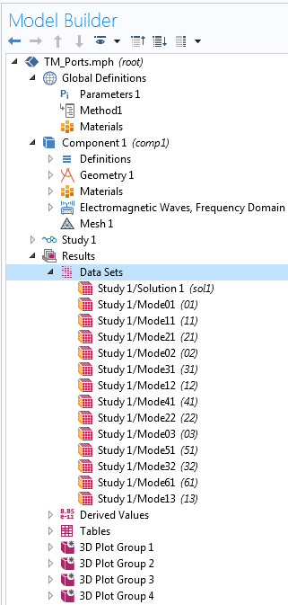
The zeroes of the Bessel function for each mode number are entered as parameters (left). These parameters are used in method 1 (shown below) to compute the solution sets for each mode number (right), just above the cutoff frequency.
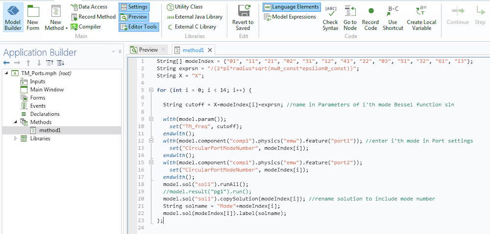
A method used to streamline the solution process for TM modes. We are able to automate the plot generation for each mode using similar methods.
Closing Remarks
This blog post has outlined how to use circular ports for waveguide excitation and termination. While only circular ports are discussed here, remember that cutoff frequency must be considered when using other port types as well. The only difference for rectangular and coaxial ports is their respective cutoff frequency equations, which are still a function of the mode number and port dimensions. You can visualize the mode shapes for these port types efficiently by implementing similar methods.
If you have a question about modeling circular ports, please contact COMSOL Support.
Next Step
Try modeling the polarized circular waveguide featured in this blog post by clicking the button below, which will take you to the Application Gallery. Once there, you can log into your COMSOL Access account and download the MPH file.
References
- David M. Pozar, Microwave Engineering, John Wiley & Sons, 1998.
- Constantine A. Balanis, Advanced Engineering Electromagnetics, John Wiley & Sons, 1999.




Comments (1)
Virginia
April 20, 2022HELLO, THANK YOU FOR THIS USEFUL INFORMATION, I HAVE A QUESTION, WICH MEANS THIS FREQUENCY IN THE MODEL :
range(0.9*frq,(1.5*frq-(0.9*frq))/10,1.5*frq)