Electron guns are frequently used in cathode ray tubes, electron microscopes, spectrometers, and particle accelerators. The electron gun extracts electrons from a hot cathode or a plasma, then accelerates them to a high kinetic energy. One of the main design challenges in building an electron gun is that the electrons repel each other, so the beam tends to spread out. Here, we discuss modeling one of the earliest electrode configurations that was devised to counteract this electrostatic repulsion: the Pierce electron gun.
Electron Gun Design
A good electron gun design must be able to do the following:
- Extract a sufficiently high number of electrons; that is, get an adequate beam current
- Accelerate the electrons to a certain kinetic energy
- Focus the beam at a particular location
Often, the electrons are rather slow when they are first emitted from the cathode or plasma source, and then they get accelerated by external fields. One very simple means of acceleration is to send the beam through a metal grid held at a fixed electric potential.
Force Between Two Charged Particles
All of the emitted beam electrons exert repulsive forces on each other. Consider two charged particles at positions r1 and r2, with charges q1 and q2. The force exerted on particle 1 by particle 2 is given by Coulomb’s law,
where ε0 = 8.854187817 × 10⁻¹² F/m is a physical constant called the permittivity of vacuum.
If q1 and q2 have the same sign — that is, both particles are either positively or negatively charged — then the force on particle 1 points away from particle 2. If one particle is positively charged and the other is negatively charged, then the force on particle 1 will point toward particle 2. Thus, like charges repel, while opposites attract.
The attractive or repulsive force gets stronger as the particles move closer together. If you divide the distance between two electrons in half, the repulsive force they exert on each other increases by a factor of four.
Force Between Many Charged Particles
Most real-world systems include a huge number of electrons, not just two. The total Coulomb force acting on an electron is the sum over the forces exerted by all other particles. For example, the total force acting on the first particle is
where N is the total number of electrons.
Imagine a cylindrical beam containing many electrons. For an electron near the center of the beam, there are an equal number of other electrons on any side, so if we take the vector sum of the forces acting on this electron, the Coulomb forces will mostly cancel out. On the other hand, for an electron near the edge of the beam, the net force will push it even farther away from the center. So, if the beam electrons are initially moving parallel to each other, they will begin to spread out, or diverge, as the beam propagates.

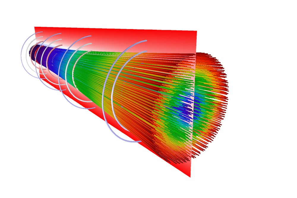
A diverging electron beam. The beam is released at a waist (left) where the electron velocities are parallel. At the right side, the electrons are spreading out in all directions.
To see some examples that demonstrate how an electron beam diverges in free space, see the tutorial models Electron Beam Divergence Due to Self Potential and Relativistic Diverging Electron Beam.
The repulsive force that causes the beam to spread out is strongest where the beam electrons are slowest, because those regions tend to have the highest charge density. Therefore, one of the key technical challenges in designing an electron gun is often keeping the beam focused in the first acceleration gap, immediately after the beam electrons are emitted (Ref. 1).
Finding the Optimal Electrode Shape
Our goal is to design an electron gun geometry so that the shape of the electrodes cancels out the Coulomb repulsion between the beam electrons, so that the beam goes in a straight line without spreading out.
To begin, consider a two-dimensional sheet beam that is uniform in the out-of-plane (z) direction. The beam will propagate in the positive y direction. The beam electrons are first emitted from a cathode (V = 0) located at y = 0 and are attracted toward an anode (V = Va) located at some height y = d.
Let’s begin with a trivial solution, where the beam is infinitely wide in the x direction. In this case, any beam electron could be considered to be at the center of the beam, and the electric forces to the left and the right will cancel each other out.

Simple sheet beam between two flat electrodes, extending infinitely in the +x and –x directions.
There is a theoretical maximum amount of current that can be extracted from the cathode without causing electrons to be repelled backward. This is called the space charge limit, and a cathode releasing electrons at this current is space charge limited. During space-charge-limited emission between two parallel electrodes, the electric potential in the gap follows the distribution given by Child’s law (Ref. 2),
Now suppose the electrons are only flowing in the region x < 0, and that there are no charges in the region x > 0.

If the electrodes retained their flat shapes, then because of the electrostatic repulsion in the beam, some of the electrons close to the y-axis would spill into the region x > 0.

Thus, divergence or spreading of an electron beam occurs when the beam has a finite size, because electrons near the edge of the beam feel an imbalance in the Coulomb forces from other electrons. In the next section, we introduce an analytic approach to change the shape of the electrodes so that the beam goes directly upward and no electrons spill into the region x > 0.
The Pierce Method of Electron Gun Design
Suppose that the cathode and anode are still flat in the region x < 0, but now they take on different shapes in the region x > 0. The exact functional forms of these electrode shapes are not yet known.

Because there are no charges in the region x > 0, the electric potential must satisfy Laplace’s equation,
Consider the complex number u = y + ix. Pierce’s method (Ref. 1, 3) begins with the observation that any twice-differentiable function of u — let’s call it f(u) — will also satisfy Laplace’s equation. This can be proven by repeated application of the chain rule,
\frac{\partial^2 f}{\partial x^2} + \frac{\partial^2 f}{\partial y^2}
&= \frac{\partial}{\partial x}\left(\frac{\partial u}{\partial x}\frac{\partial f}{\partial u}\right)
+\frac{\partial}{\partial y}\left(\frac{\partial u}{\partial y}\frac{\partial f}{\partial u}\right)\\
&= \frac{\partial}{\partial x}\left(i\frac{\partial f}{\partial u}\right)
+\frac{\partial}{\partial y}\left(\frac{\partial f}{\partial u}\right)\\
&= \frac{\partial u}{\partial x}\frac{\partial}{\partial u}\left(i\frac{\partial f}{\partial u}\right)
+\frac{\partial u}{\partial y}\frac{\partial}{\partial u}\left(\frac{\partial f}{\partial u}\right)\\
&= i^2\frac{\partial^2 f}{\partial u^2} + \frac{\partial^2 f}{\partial u^2}\\
&= -\frac{\partial^2 f}{\partial u^2} + \frac{\partial^2 f}{\partial u^2}\\
&= 0
\end{align}
With this in mind, let the electric potential in the region x > 0 be defined as the real part of f,
Then V will also satisfy Laplace’s equation in this charge-free region. To ensure that the electric potential is continuous at x = 0, V must satisfy the potential distribution given by Child’s law (Ref. 2),
The cathode is simply the set of coordinates in the complex plane that satisfy this equation for V = 0. Similarly, the anode is the set of coordinates in the complex plane that satisfy this equation for V = Va.
At this point, it is convenient to rewrite u in cylindrical polar coordinates,
Note that here, θ = 0 is the positive y direction rather than the x direction. Now, our expression for the electric potential in the region x > 0 is
Because r and d are real, this can be simplified to
and then invoking Euler’s formula yields the final result
The shapes of the cathode and anode are now just the curves that, when inserted into the last expression, give V = 0 and V = Va, respectively.
The solution for V = 0 is the straight line
or a 67.5° angle from the beam propagation direction.
The solution for V = Va is the curve
Therefore, the Pierce gun design algorithm predicts that a beam can be kept perfectly straight using a straight cathode at a 67.5° angle from the beam propagation direction, and a curved anode.
Creating the COMSOL Multiphysics® Geometry
The anode curve found in the previous section asymptotically approaches the cathode line but never quite meets it; the perfect Pierce electron gun extends infinitely far in the positive x direction, so we have to arbitrarily cut it off at some point.
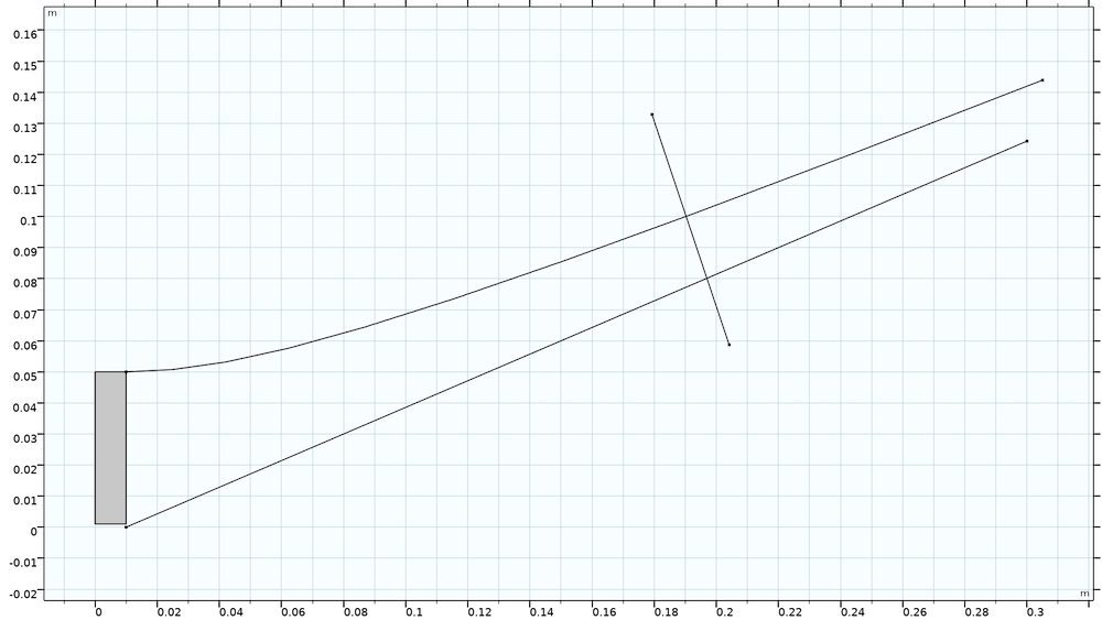
In the following plot, the long straight line is the cathode, and the long curved line above it is the anode. These two lines could be extended infinitely far but would never meet. So, for a more practical model, we draw another line that intersects both the cathode and anode, then use the Convert to Solid operation in COMSOL Multiphysics® to form a domain bounded by these curves. The intersecting line segment is drawn perpendicular to the cathode because we expect the electric field to point in this direction.
The solid rectangle on the left side is the beam propagation region, and the line x = 0 is a symmetry axis here. So the complete Pierce gun geometry has the same curved anode shape on either side of the beam.

Pierce electron gun geometry, just before truncating the cathode and anode curves.
Particle Field Interaction Modeling
In this model, we use the dedicated Space Charge Limited Emission multiphysics coupling node to release a space-charge-limited beam of electrons in the positive y direction. Then, to include the effect of mutual electrostatic repulsion between the beam electrons, we use the dedicated Electric Particle Field Interaction multiphysics coupling. This causes the beam electrons to contribute to the space charge density in the domain, which is then included in the Electrostatics interface when solving for the electric potential.
The final algorithm for getting a self-consistent solution for the electric potential and the particle trajectories then looks like this:
- Trace the particles, without considering the electrostatic repulsion between the beam electrons. From this solution, estimate the space charge density in the beam.
- Using the estimated space charge density, as well as the boundary conditions at the cathode and anode surfaces, compute the stationary electric potential.
- Use the electric potential from the previous step to define an Electric Force on the particles. Trace the particles again, and compute the space charge density in the beam.
- Continue alternating between steps 2 and 3 for a fixed number of iterations or until the solution doesn’t noticeably change between iterations.
Results
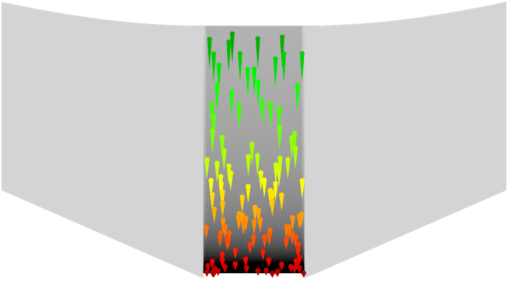
A Mirror dataset was used to reflect the electric potential distribution across the y-axis. The following plot shows the particle trajectories, colored according to their speed with green being the fastest. The space charge density in the domain is plotted in grayscale, with darker shades indicating greater charge density. It is clear that the charge density is greatest in a narrow region adjacent to the cathode, and decreases as the particles accelerate.

Electric potential distribution and particle trajectories in the Pierce gun.
The following animation shows how the particles accelerate as they approach the anode. Here, the grayscale background shows some equipotential contours. The particles in the beam area move in straight lines, and the equipotential contours in the beam cross section are horizontal — both good indications that the inclined cathode and curved anode are correctly counterbalancing the electrostatic repulsion in the beam.
Try It Yourself
To download the Pierce Electron Gun model, click the button below.
Further Reading
An additional benchmark model, providing some helpful theoretical details about Child’s law and its derivation, is the Child’s Law Benchmark tutorial.
Child’s law is based on a simplifying approximation that neglects the thermal velocity of the released electrons. In reality, particles at room temperature can fly around at speeds of several hundred meters per second, immediately after leaving the cathode. To learn more about the thermal distribution of emitted electrons and its effect on space charge limited electron emission — sometimes called the Langmuir–Fry model (Refs. 4, 5) — see the example Thermionic Emission in a Planar Diode.
References
- S. Humphries, Stanley, Charged Particle Beams, Dover, 2013.
- J.R. Pierce, “Rectilinear electron flow in beams”, Journal of Applied Physics, vol. 11, no. 8 pp. 548–554, 1940.
- C.D. Child, “Discharge from hot CaO”, Physical Review (Series I), vol. 32, no. 5, pp. 492–511, 1911.
- T.C. Fry, “The thermionic current between parallel plane electrodes; velocities of emission distributed according to Maxwell’s law”, Physical Review, vol. 17, no. 4, pp. 441–452, 1921.
- I. Langmuir, “The effect of space charge and initial velocities on the potential distribution and thermionic current between parallel plane electrodes”, Physical Review, vol. 21, no. 4, pp. 419–435, 1923.


Comments (5)
naveed ahmed
April 8, 2021Hi dear Christopher ,
I am working on a charge particle tracing module and want to emits electrons one after another like a beam. But in my case all the electrons emits at the same time. I tried every possible way but no success. I want to emit electrons one after another, like you show in figure (Electric potential distribution and particle trajectories in the Pierce gun) and inanimations.
Harsh Goel
April 28, 2021Why doesn’t the downloadable mph model have any post-processing similar to the animation shown in the end? I want to obtain something similar.
I really need to figure this out. I’ll be obliged if I can know this. If possible please, email: 26goelh@gmail.com
Christopher Boucher
May 13, 2021 COMSOL EmployeeHi All,
Several readers have asked how to reproduce the final animation in this blog post, which shows electrons being released from the cathode at unequal times. The Application Library example treats each model particle as representing the continuous release of a fixed number of electrons per unit time, which leaves behind a trail of space charge density in all the mesh elements it passes through. So all model particles appear to be released at time t=0.
To demonstrate how this last animation was generated, please click “Get the Tutorial Model” above and look for the model file “pierce_electron_gun_with_custom_plots”. The key is to add another instance of the Charged Particle Tracing interface which takes the field from the previous study but is not bidirectionally coupled to it. Then, you can freely release particles at multiple times. Thanks for reading!
Chris
Adrian Garcia
February 17, 2024Hello, because comsol has not created in the domain the ability to model the loss of speed when an electron or a charged particle enters a magnetic field, and loses speed by emitting radiation, you are missing that, in tracing charged particles, that would make you earn more money from companies
Antariksh Nawander
February 29, 2024Why am I not able to download the pdf file associated with the model? It shows a proxy error when downloading a pdf to any of the models.