
In a previous blog post, we discussed why surfaces are special in chemical reactors. In this blog post, we’ll see how surface area is maximized in reactor structures such as pellet beds, and how we can simply and accurately simulate fixed-bed reactors in spite of their local geometric complexity and the importance of microscopic diffusion.
Porous Catalysts and Homogenized Models
When a reaction takes place at a surface, the overall rate of conversion of the chemical reactant is given by the product of the flux of the chemical species with the area of the surface. So, the greater the surface area, the faster the overall conversion.
You might remember from introductory chemistry that the overall rate of a chemical reaction can be increased by making more surface area available for reaction. One way to do this is to use a porous structure containing small pellets or channels. The pores allow transport of a solution-phase chemical species by convection and diffusion, while the pore boundaries act as active catalytic surfaces.
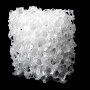
A microstructure of a porous material. Image by Onnovisser1979 — Own work. Licensed under CC BY-SA 3.0, via Wikimedia Commons. Image has been cropped for this blog post.
When modeling porous media, it’s common to use a homogenization approach. Rather than including the intricate microscopic detail of the porous medium, its properties can be averaged out and represented as uniform. We can still study variation in quantities like concentration, flow velocity, and temperature between one part of the pellet bed and another, even if the bed properties themselves are uniform. For some more detail on this modeling approach, see my colleague Ed’s blog post on heterogeneous catalysis.
There are several important properties of the porous medium:
- Porosity: the ratio of void (fluid) volume to total volume
- Permeability: the ratio of flow rate to flow driving force, quantifying the drag exerted by surfaces in the porous medium
- Tortuosity: the ratio of real diffusion length to point-to-point displacement, quantifying the lower effective diffusivity due to nonlinear diffusion paths
When studying surface reactions, another property becomes important: the specific surface area (SSA). This is the reactive surface area contained within a unit volume of the porous material. Its units are m2/m3, or equivalently, 1/m.
In a homogenized model of a porous medium, reaction rates are given per unit volume of the porous material. The real reaction rate on the surface (Nm, mol m-2 s-1) must be multiplied by the specific surface area to give the effective volumetric reaction rate (Rm, mol m-3 s-1):
Recall from Part 1 of this blog series that the flux for the surface reaction typically depends on a rate constant with units m s-1. Then, the effective rate of a first-order reaction in a porous medium can be given as follows:
where c is the concentration of reactant (mol m-3) and
where km is the “true” rate constant (m s-1).
It is clear from this equation that a heterogeneous reaction occurring at the surfaces of a porous medium can be understood in the same way as a homogeneous process in a uniform medium, with an apparent rate that scales with both the chemical kinetics of the reaction and the specific surface area.
Ideal Square-Channel Reactor: An Example of Assessing Porous Medium Properties
To understand the relationships between the different effective properties of a porous reactor, let’s consider a simple example. The figure below illustrates a reactor with parallel, square channels in which the green regions are fluid and a reaction can take place at the interface with the white regions (solid).
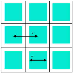
Schematic of a cross-sectional view of a reactor with parallel square channels.
How can we compute the specific surface area and other homogenized properties of this reactor? The reactor cross section has square unit cells of side length d, in which the fluid cross-sectional area is the cross-sectional area of one channel, and the effective surface area per unit length is the perimeter of one channel. Hence, the porosity is:
and the specific surface area is
Note that for like porosity, narrower channels give higher surface area, as would be expected.
What will the permeability be? Permeability can be defined as:
The effective velocity is given by the product of real velocity with porosity. From Darcy’s law for a square channel, the real velocity relates to viscosity μ and pressure gradient as:
Hence:
So, for like porosity, a linear increase in specific surface area will cause a quadratic decrease in permeability, hence a corresponding decrease in flow rate at like overpressure. For this reason, the overall chemical and mechanical design of a porous reactor may require a channel size that strikes a good balance between flow resistance and overall rate of reaction.
One final point to consider is diffusion. In computing an effective kinetic rate constant for a reaction at the surfaces within a homogenized porous medium, we assumed that the pores are small enough that the diffusion could be considered a constant locally. What are the actual requirements here?
In the presence of flow, convection would normally dominate the mass transport, but convection cannot be responsible for the limiting rate of reaction at a catalytic surface. The flow velocity into the surface is zero for dilute reactants, so only diffusion can bring material from the bulk flow (the centerline of a flow channel, for example) to the reacting surface. If this rate of diffusion is too slow, the specific surface area of a porous bed may not be well utilized.
For the case of the channel with a square cross section, the time for diffusion can be considered by comparison to a cylinder of like cross-sectional area. The required time for diffusion out-of-plane of the channel centerline depends on the square of the effective radius:
For good utilization of the catalyst surface, we would require:
so
where U is the average (real) velocity.
It is clear that smaller channels strongly encourage better diffusive mixing and raise the achievable overall rate of reaction in a porous medium.
Porous Media in a Catalytic Convertor
The square-channel reactor above resembles the overall design of the active region of a catalytic converter. Catalytic converters are used in auto exhausts to break down polluting gases such as nitrogen oxides (NOx). In a typical design, the active region of a catalytic converter is called a monolith. This is a structure of parallel, narrow channels in which the catalyst is coated on the channel surfaces (washcoat), maximizing the area for catalytic reaction of the gas.
The ideal reactor described above would give very poor performance in a real application, however. In a monolith, the washcoat itself is highly porous, further increasing the specific surface area, and hence the overall rate of reaction. Accordingly, the expression for specific surface area above should be increased with a multiplying quantity representing the microporosity of the washcoat.
In the tutorial example Analysis of NOx Reaction Kinetics, the monolith is represented as a porous domain, and the gas flow is described using a characteristic permeability. Since the pores have a definite direction along the monolith in this case, a tortuosity correction is not included. Instead, the free flow diffusion coefficient is applied for transport in the flow direction, but diffusion is neglected in the out-of-plane direction due to the walls of the narrow channels that form the monolith.

Anisotropic specification of the diffusion coefficient in a model of a monolithic reactor, representing diffusion only in the direction of the microchannel and zero diffusion in the normal plane.
This tutorial example combines diffusion, convection, and reaction in the monolith with a model of the fluid flow in porous media using Darcy’s law, as well as a heat transfer model combining convection with heat conduction through both the solid and gas phases of the porous monolith. Below, you can see a prediction of the degree of conversion of NOx in the catalytic reactor, confirming that a large percentage of these pollutants are removed.
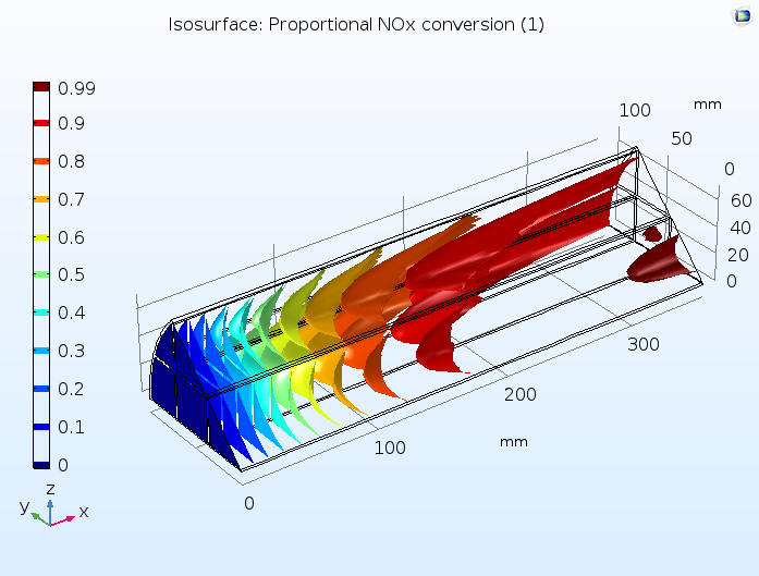
Proportion of NOx conversion in the monolith of a catalytic converter, where the monolith is modeled as a homogeneous porous medium.
A reactor designer could use the COMSOL Multiphysics® software to create a detailed porous reactor model to optimize flow rate and catalyst distribution, as well as evaluate temperature dependence, mechanical stress, and other important engineering aspects of the design.
Homogenization at Several Length Scales: Reactive Pellet Bed
The monolith of a catalytic converter is a typical example of a reactor with porosity on multiple length scales. Also, in Ed’s blog post, mentioned earlier, he explained that the catalyst particles that make up a packed bed may themselves be porous. The micropores within each catalyst particle create additional reactive surface area; meanwhile, there are also pores between the catalyst particles in the packed bed through which the liquid or gas can flow.
A homogenized treatment of the combined microporous-macroporous model is provided with the built-in Reactive Pellet Bed feature in the Chemical Reaction Engineering Module. This feature adds diffusion in an extra dimension to a 2D or 3D porous medium in a Transport of Diluted Species interface. Typically, this extra dimension is the radius of a near-spherical catalyst particle (or the effective radius of a nonspherical particle).
The Multiscale 3D Packed Bed Reactor tutorial model illustrates how to use the Reactive Pellet Bed feature. In the screen capture from the Settings pane for the feature, you can see that physical properties of the pellets, such as their shape, size, and porosity, are specified. Note that here, the “Pellet porosity” refers to the microporosity of the catalyst particles themselves, not the porosity of the pellet bed.
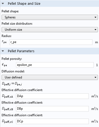
Pellet shape, size, porosity, and diffusion settings in a Reactive Pellet Bed feature.
As discussed in the analysis of the monolith, the diffusion of the reactants to the outer surface of the catalyst particles is also important, since the porous flow between the catalyst particles does not penetrate the particles themselves. This means that there is a boundary layer where diffusion dominates mass transport. This boundary layer creates a difference in concentration between the average concentration at the outer surface of the pellets and the average concentration in the pores between the pellets. The Reactive Pellet Bed feature defines a prebuilt diffusive film resistance, which can be computed according to a Sherwood number for the relative contribution of convective and diffusive mass transport in the flow. Of course, as with any setting in COMSOL Multiphysics, a user-defined formula can be used instead.
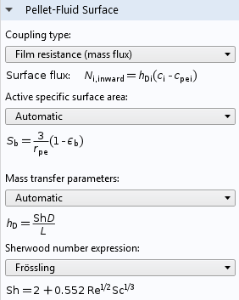
Film resistance settings for mass transport at the pellet-fluid surface of a Reactive Pellet Bed feature.
To summarize all of the processes involved, let us consider a reaction, A(aq) → B(aq), which occurs at the solid-liquid interface of the micropores of catalyst particles. The particles themselves form a packed bed through which the aqueous solution is driven under pressure. The transport and reaction processes are as follows:
- Convection-dominated transport of A(aq) from the flow inlet to the porous packed bed
- Diffusion-dominated transport of A(aq) in the pores of the packed bed to the surface of the catalyst particles
- Diffusion of A(aq) along the micropores
- Reaction of A(aq) at the micropore surface to create B(aq)
- Diffusion of B(aq) along the micropores back to the catalyst surface
- Diffusion-dominated transport of B(aq) from the surface of the catalyst particles into the solution flowing through the pores of the packed bed
- Convection-dominated transport of B(aq) from the bulk of the porous packed bed toward an outlet of the flow
Of course, we shouldn’t think of these processes as sequential — they are all happening at the same time, while the reactor is in continuous operation. Any one of these steps, whether the reaction rate itself or the constituent mass transport processes, might limit the overall rate of conversion of A to B, hence placing a maximum on the reactor throughput. Since the chemical species transport problem involves so many steps, numerical simulation is vital to predict behavior and optimize efficiency. The Reactive Pellet Bed feature allows such simulations to be defined quickly, based only on the physical and chemical properties of the reactor.
The figures below show typical outputs from a reactive pellet bed model. The first figure shows the distribution of concentration of the reactant, as averaged over the pore space between the reactive pellets. As the reactant diffuses into the pellets and reacts, this reactant concentration is consumed from left to right. The pattern of flow inlets on the left-hand side causes a nonuniform concentration profile, hence a nonuniform utilization of the catalyst.
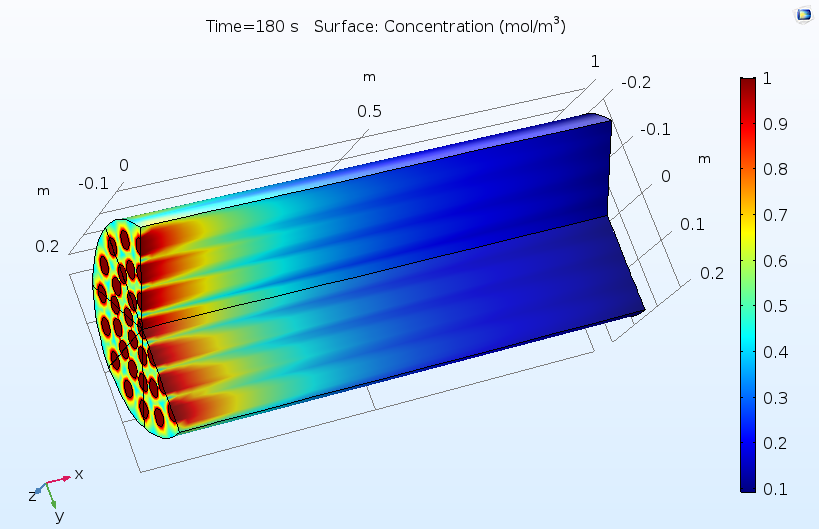
Concentration of a reactant as averaged in the pore space between reactive pellets in a reactive pellet bed.
The data below shows a more quantitative analysis of the pellet bed, considering both pore and pellet concentrations for the reactants A and B and the product species C. The nonuniform pellet concentration of species C, with a maximum in the middle of the bed, indicates that the catalytic reaction proceeds more rapidly in a specific region of the catalyst bed. The evaluation of the extent of a reaction zone in a packed bed, as well as how the location of this reaction zone changes over time, can ensure maximum efficiency in utilization of the catalyst and optimal total conversion of reactant to product.
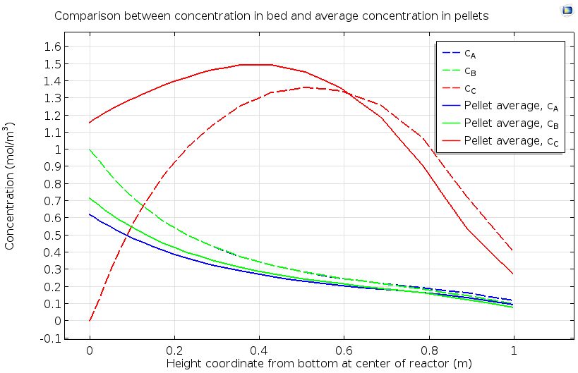
Concentration of reactants A and B and product C as averaged in the pore space between reactive pellets, and within the reactive pellets, in a reactive pellet bed.
Concluding Thoughts on Surface Reactions in Porous Media and Reactive Pellet Beds
In the first post in this blog series, we highlighted the particular properties of surfaces as sites of chemical reaction. Practical chemical engineering designs often involve porous media and microporous catalyst particles in order to maximize surface area. The dedicated features of the Chemical Reaction Engineering Module, an add-on to COMSOL Multiphysics, enable an easy formulation of the reactions and mass transport — as well as coupling to flow and heat transfer — that occur at the surfaces of porous materials.
Additional Resources
- Try the tutorial models mentioned in this blog post:
- Read Part 1 in this blog series on modeling surface reactions


Comments (0)