
Can a table stand without its legs touching the ground? The answer is yes, using tensegrity! Through the power of physics, tensegrity tables and their “floating” tops force us to suspend disbelief at what we are seeing. To find out how they work, let’s take a look at other tensegrity structures and then dive into a model of a tensegrity table.
Applications of Tensegrity
While the topic of who first used tensegrity as a structural technique is debated, the term “tensegrity” was coined by engineer and architect Buckminster Fuller in the 1960s, shortened from “tensional integrity”. Tensegrity refers to the structural principle founded on a system comprised of individual rigid components such as tubes or beams and flexible components like wires or cables. The rigid elements are under continuous compression and do not touch each other; instead, they are held together by the flexible elements, which are under continuous tension. This creates an internal stability that allows the structure to support itself without expected necessities like foundations, joints, or columns. Due to the interconnected nature of tensegrity, each part is essential to the function of the larger whole.
Before civil engineers capitalized on tensegrity to build architectural structures like geodesic domes, the principle could be seen in simple structures like bicycle tires and even in nature: in spider webs, for example.

Tensegrity structures use few materials, making them lightweight and adaptable, with the potential for use in eco-friendly architectural design. That said, engineers have held off on using tensegrity structures in residential buildings like houses, as they do have a weakness to phenomena such as seismic disruption. Today, tensegrity structures are often used in a supplementary capacity, such as in the Olympic Stadium in Munich, Germany, where the stadium itself is not built with tensegrity, but the roof is. Steel cables and acrylic glass held together using tensegrity make an aesthetically pleasing webbed design that combats wind and snow.
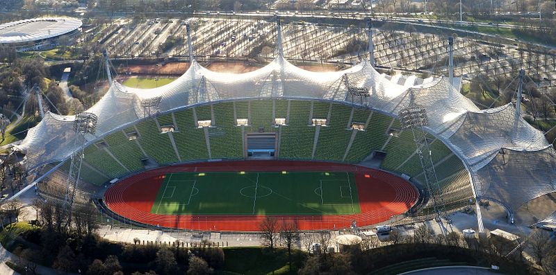
Olympic Stadium in Munich, Germany, where the roof is built using tensegrity. This file is licensed under the Creative Commons Attribution-Share Alike 3.0 Unported license, via Wikimedia Commons.
To show off more of what tensegrity structures can do, let’s take a look at two more examples…
Towers and Robots
Outside the Hirshhorn Museum in Washington D.C., a 60-foot sculpture made of steel and aluminum with only 14 inches of ground contact — dubbed Needle Tower by artist Kenneth Snelson (a student of Fuller’s) — manages to stay upright using tensegrity, or what Snelson described as “floating compression”.
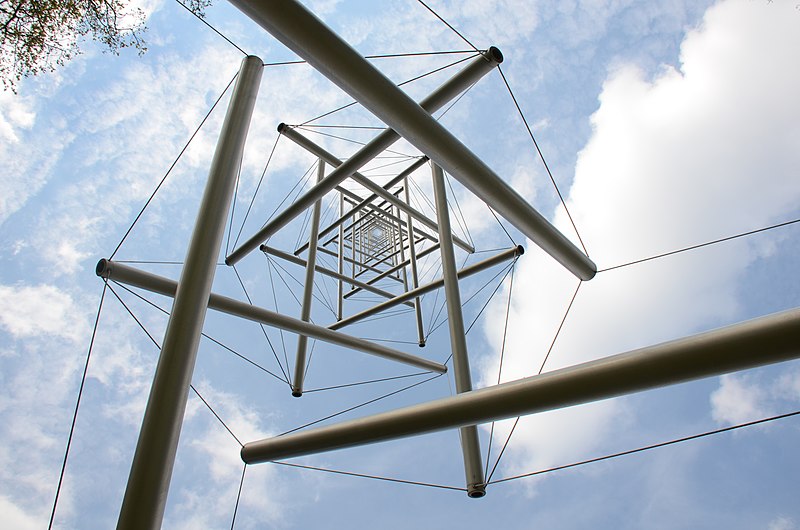
Kenneth Snelson’s Needle Tower (1968) outside the Hirshhorn Museum in Washington, D.C. Photo by Henk Monster, licensed under the Creative Commons Attribution 3.0 Unported license, via Wikimedia Commons.
Needle Tower is displayed such that guests will pass it on their way from the National Air and Space Museum, where they may have learned about another tensegrity structure at work: the NASA Super Ball Bot.
The Super Ball Bot is a prototype robot NASA designed for planetary landing and exploration that works off of tensegrity principles. Simply made of cable wire and rods, the robot moves around in any direction by changing the cable lengths and consequently the tension, pulling the rods so the robot can traverse unpredictable landscapes. The elasticity of the structure absorbs impact force and allows it to be dropped onto surfaces without needing an airbag.
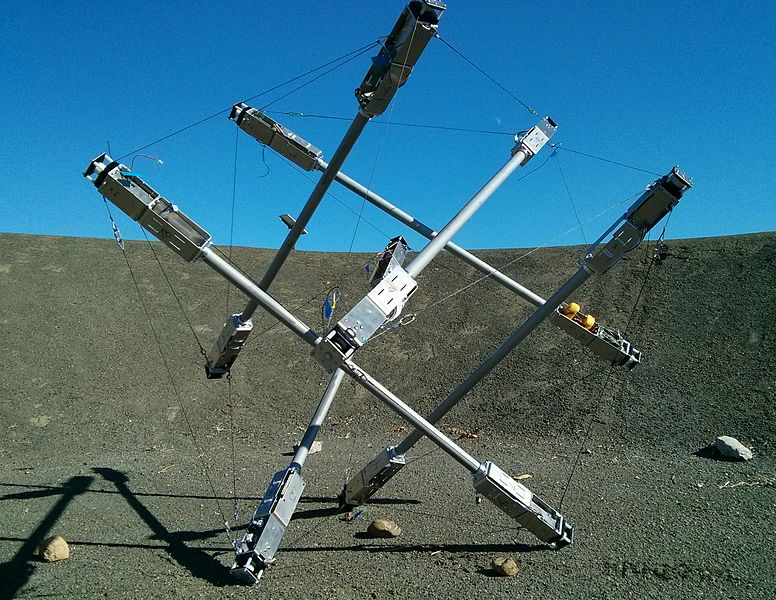
The NASA Super Ball Bot. This file is licensed under the Creative Commons Attribution-Share Alike 4.0 International license, via Wikimedia Commons.
While these examples are pretty out of this world, tensegrity doesn’t have to involve 60-foot sculptures and interplanetary exploration robots. The underlying principles of tensegrity are simple and accessible — so accessible that you can keep an example of tensegrity at work right in your own home! Tensegrity tables, or “floating tables”, function on the most basic application of tensegrity: a fixed component held aloft by a flexible component under tension. To show how floating tables work, we made a model using the COMSOL Multiphysics® software that analyzes the stresses placed on the wires that hold the tension. Let’s a take a look at what makes this table float!
Composition of a Floating Table
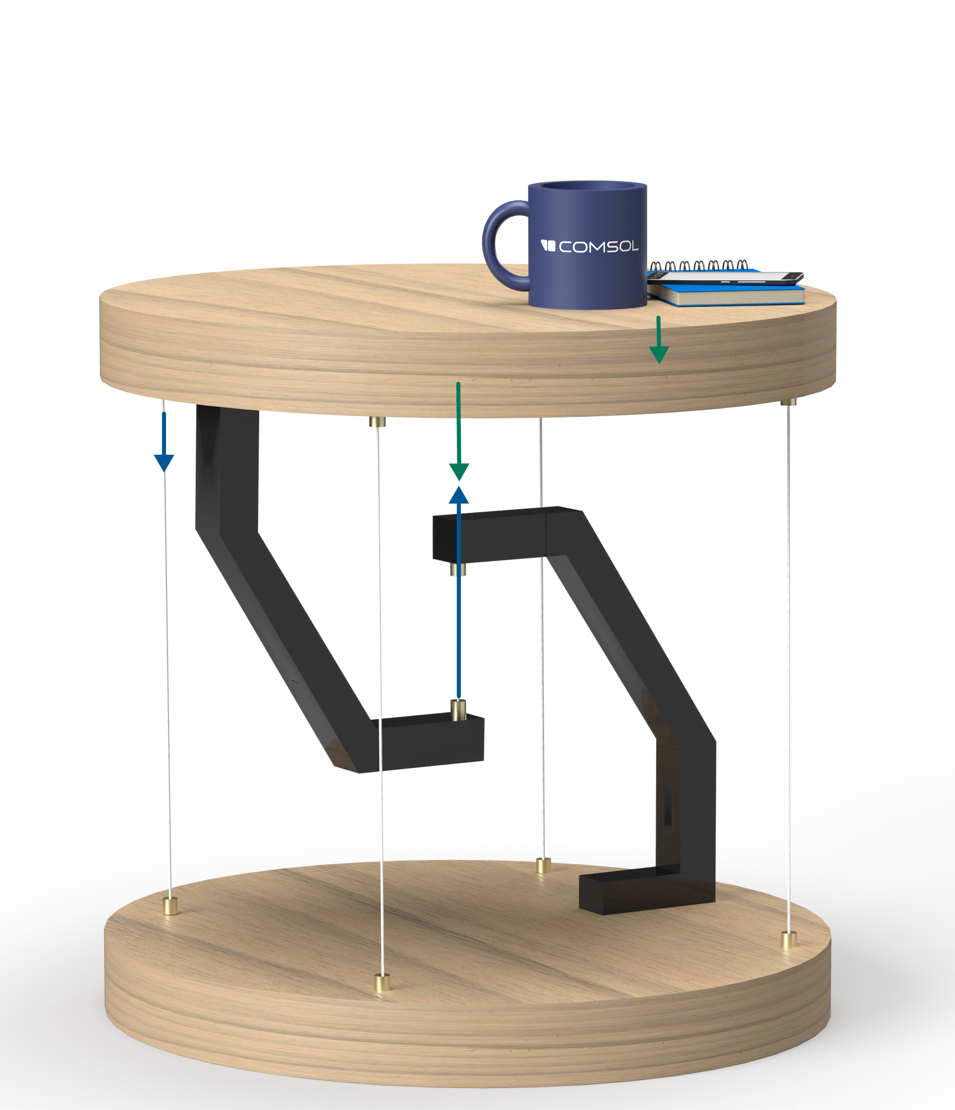
The simplest tensegrity table is made of two rigid pieces: the upper portion (the tabletop and an affixed bent leg extending downward) and the lower portion (the base of the table and a leg extending upward). A wire connects the two legs so that when gravity pulls the top portion downward, tension in the wire prevents the upper leg from falling to the ground.
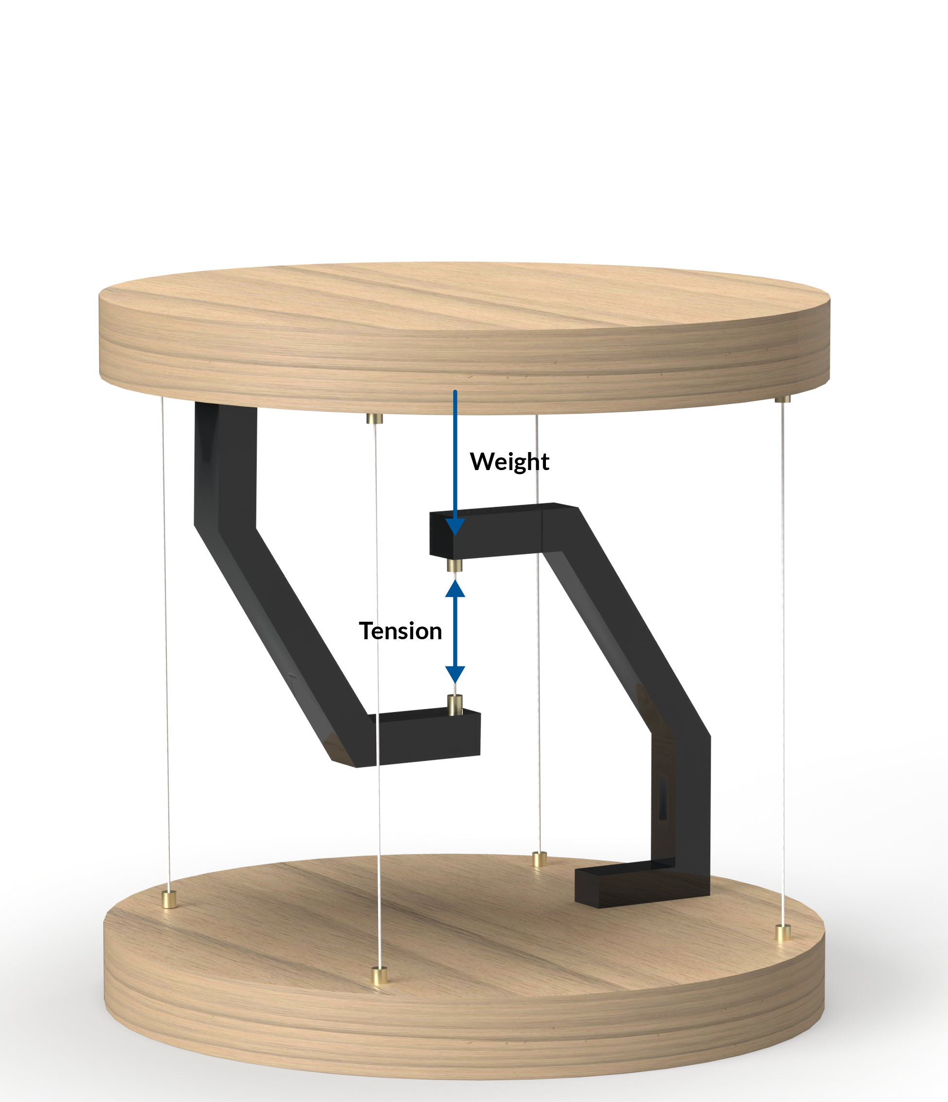
Gravity is counteracted by tension in a tensegrity table.
Although the single central wire hangs the top portion from the bottom portion of the table, supporting wires connecting the the edges of the tabletop to the edges of the base are required to prevent the tabletop from tipping over. These supporting wires are usually under little tension when the weight of the tabletop is evenly distributed. If an object is placed toward one edge of the tabletop, applying more downward force on the area, the wire(s) on the opposing edge will be put under more tension to keep the table level.
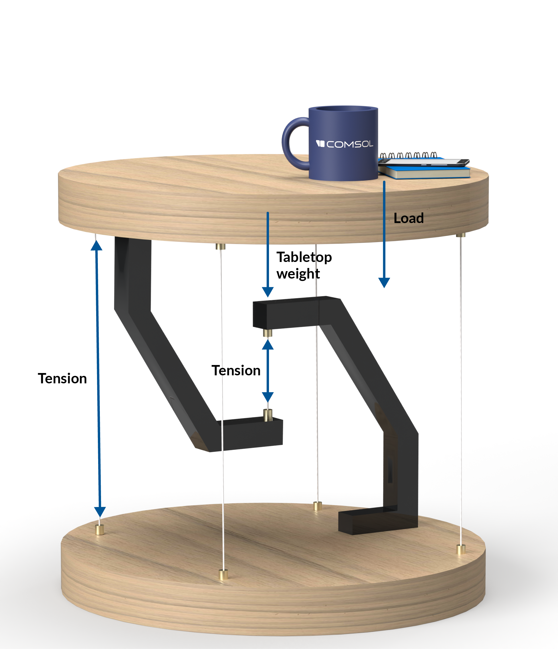
Outer wires stabilizing a tensegrity table.
All forces balancing the upper part of the table are indicated.
Fun fact: The design of tensegrity tables (like the one depicted above) is often symmetrical, so they can be turned upside down and will still work the same way.
Tensegrity in Action
The tensegrity table in our example model is composed of wood with a density of 500 kg/m3. The material is considered to be rigid. The single central and four outer strings are made of steel. The legs here are interlocked but not touching, held together only by the wire through the center.
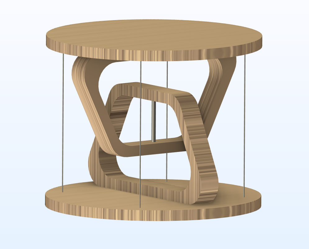
Tensegrity table geometry.
This model analyzes two load cases in addition to the self-weight load already provided by the table itself. The first case models a load placed on top of the table, acting vertically downward at varying magnitudes. In the second case, a twisting moment is applied, as if the tabletop were to be spun like a bottle cap, which creates tension in the wires. Both cases model the applied load alongside the weight of the table using the Wire interface, which provides functionality for analyzing systems of cables or wires, both separately and in conjunction with other types of structures.
Vertical Loading
The first load is a compressive force pushing vertically downward with a magnitude varying between 0 and 500 N, applied evenly to the top of the table. The central wire takes the load, while the outer strings have zero levels of force applied. Unless the table tilts one way or another, the surrounding wires will continue to remain at little to no tension.
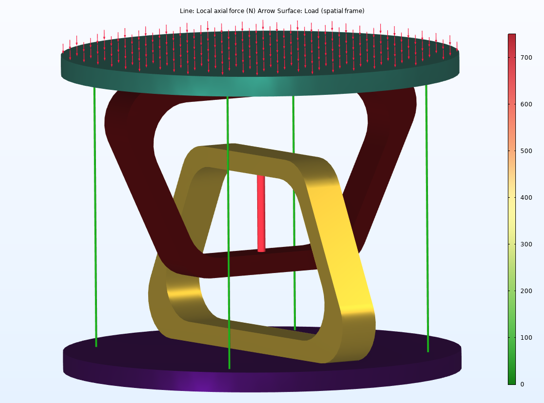
Vertical loading on the tensegrity table.
Twisting Moment
In the second case, a twisting moment of 10 N/m is applied. Like the previous case, the applied load, along with the weight of the table, is supported by the central wire. Due to the addition of the twisting moment rather than a straight downward force, the outer strings are also in tension albeit at very low levels.
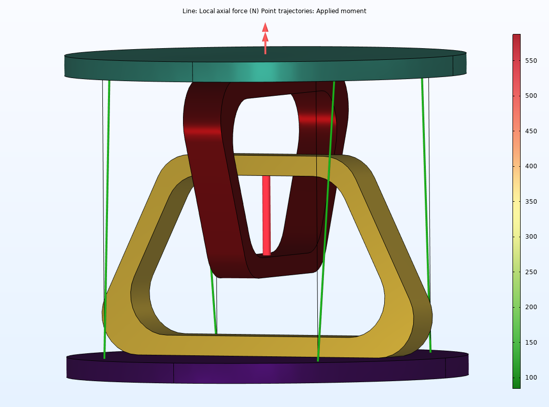
Twisting moment on the tensegrity table.
Tensegrity in the Future
Now that we’ve seen tensegrity in one of its simplest forms and understand the basic principles, it’s possible to model more complicated structures. Complex applications of tensegrity can be found in all sorts of things: stadiums, sculptures, and even planetary exploration robots. Moving forward, architects and engineers are looking for newer, bigger applications of tensegrity structures, such as tensegrity skyscrapers. The hope is that tensegrity will provide an adaptable and strong approach to construction while using lightweight materials — and less material in general — to provide an eco-friendly building plan. Until then, you can enjoy tensegrity in your living room with a personal floating table!
Next Steps
- Download the tensegrity table model files from the Application Gallery
- Try out the functionality for analyzing cable and wire systems in COMSOL Multiphysics® with these tutorial models:


Comments (1)
Ivar KJELBERG
June 18, 2024Nice example, I suspect you might get quite some info too, by studying the Eigenmodes of this model, but there are quite some degeneracy here so it might be of interest to make each of the similar tension rod just a little different.
Furthermore, the twist to compression links would not fully show up until you use non-linear modelling, or add a little torque to unbalance the design. Or go for a full non-linear buckling analysis, mode by mode 🙂