
Fusion energy has long been sought after for its potential to deliver carbon-free and scalable commercial power. Commonwealth Fusion Systems (CFS), a fusion energy startup and spinoff of the Massachusetts Institute of Technology (MIT), has showcased the potential of high-temperature superconductor (HTS) magnets and high-field tokamaks for fusion machines. However, despite these advancements, there are still a variety of challenges that come with creating a tokamak capable of generating fusion power for widespread use. To address this, CFS turned to multiphysics modeling to gain an understanding of material limitations and inform the design of their prospective high-field tokamaks.
Unlocking the Power of Tokamaks: Fusion on a Smaller Scale
Tokamaks achieve higher fusion gain — the ratio of the fusion power it creates to the power it requires to function — by growing in size and/or utilizing greater magnetic fields. Until recently, superconducting magnet technology limited the ability of tokamaks to take advantage of the latter, forcing developers to create massive examples, such as the International Thermonuclear Experimental Reactor (ITER), to achieve higher fusion gain. As an alternative, CFS and MIT explored Alcator tokamaks, which consist of copper magnets and higher magnetic fields. However, these tokamaks only traded size issues for the limitations of copper, a resistant material that consumes significantly more power to operate than previous designs. Therefore, this alternative wasn’t a viable option for economic fusion power, explained Dan Brunner, co-founder and fusion technical fellow of CFS, during a keynote talk from COMSOL Day: Nuclear Fusion.
Next, CFS and MIT collaborated to create a high-field tokamak, one that can take advantage of greater magnetic fields, without the size issues or limitations of previous designs, through the use of HTS materials. To do so, they built and used a full-performance, nearly full-scale HTS magnet. CFS is now working toward SPARC, a proof-of-concept tokamak whose target is a net fusion gain. Beyond this, CFS targets the early 2030s for the creation of ARC, a power plant designed to put fusion power on the grid. Before this step can be achieved, CFS continues to develop their understanding of SPARC through simulation.
“Now we can envision a different path from where you had to go from big to bigger to where you can just go a little bit bigger but use higher magnetic fields to create a viable fusion reactor,” said Brunner.
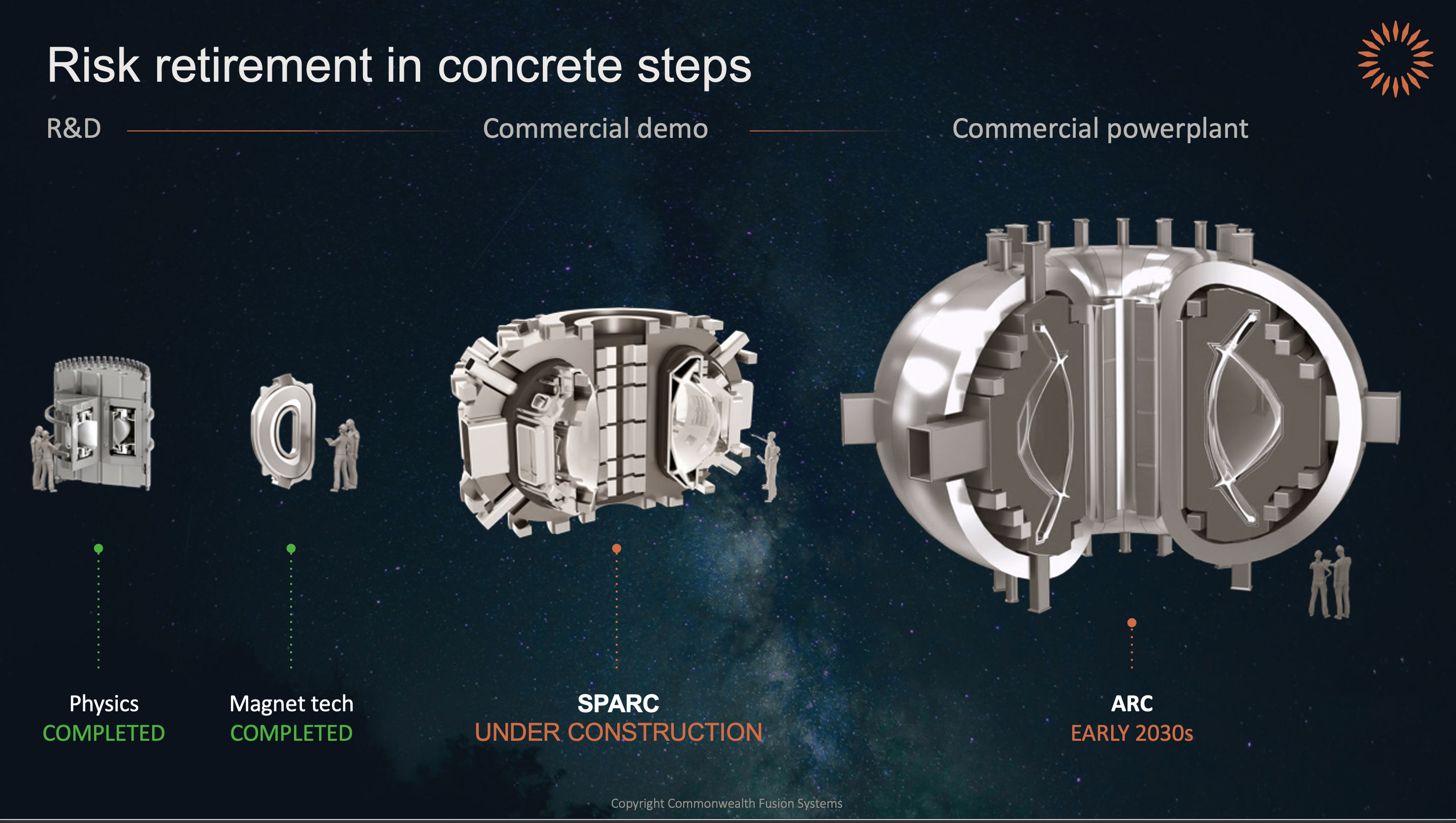
Figure 1. CFS’ prospective timeline for their ARC fusion device. Image courtesy of CFS.
Overcoming Fusion Hurdles with Simulation
Modeling tokamaks is a notoriously challenging project but, despite this, CFS has been able to break down their designs system by system, simulate the forces within, and observe complex phenomena with the COMSOL Multiphysics® software.
Calculating Coolant and Cooling Systems
Superconductors need to be maintained at cryogenic temperatures to function and avoid thermal runaway events like quenching. By necessity, these superconductors operate in the close vicinity of the almost unimaginably intense power source from fusion going on within SPARC, which makes this a challenge. CFS turned to simulation to help trial potential solutions. “Cooling is of utmost importance because there are many different sources of energy that can get into the superconductor,” said Brunner. “You need to flow cryogen through it to keep it within thermal temperature operating range.”
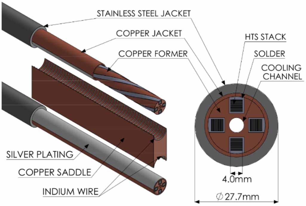
Figure 2. Cables within SPARC will feature the flow of cryogenic fluid in order to maintain the temperature of the superconductor. Image courtesy of CFS.
Brunner and his team modeled three of the most common cryogenic fluids (hydrogen, helium, and neon) at the temperature ranges they would experience in SPARC and then looked at the output of their thermal simulations. From this data, Brunner and his team were able to explore the tradeoffs of the different types of cooling systems they could use without ever exposing any superconductors or other materials to needless risk.
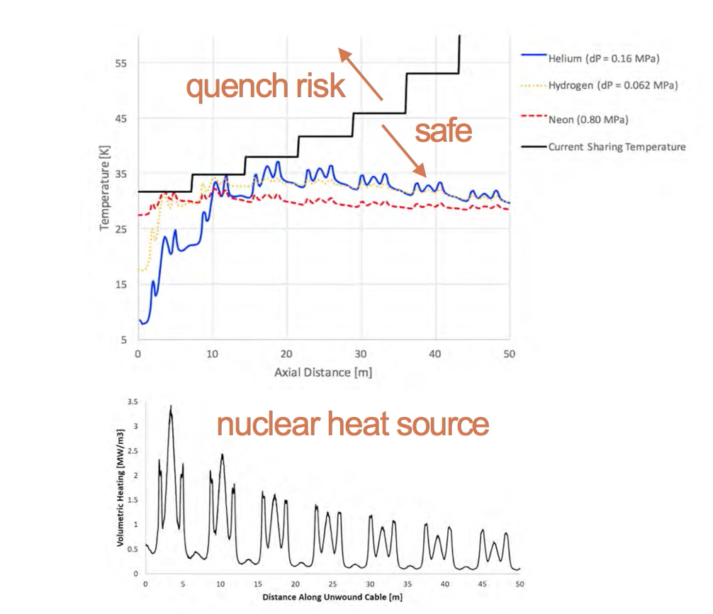
Figure 3. Fusion heat puts a great deal of energy into cables and threatens to quench the superconductor. This brings on the need to trial different cryogenic fluids. Image courtesy of CFS.
Measuring the Strength of Materials in the Right Conditions
Aside from cooling, simulation has played an important role in providing information on the forces that materials will experience within SPARC. Typically, high-field tokamaks push their structures to extremes, and this is especially true for HTS designs because of their strong magnetic field. Forces increase on structures as the square of the magnetic field, which puts plenty of strain on materials throughout the tokamak. Superconductors and their naturally low strain limits only further the need for simulation to measure the expected forces.
The current crossed with the magnetic field creates a force on the coils that the structure needs to be able to handle. CFS found that their multiphysics models were able to assess the strength and stiffness limits of different alloys at the cryogenic temperatures (about 20 K) to which they would be exposed, thus informing the future design of SPARC. By simulating the forces that these machines will endure, CFS can establish clear stress and strain limits that their designs must be able to withstand.
Managing Forces on the Vacuum Vessel
Simulation has also been used by CFS to optimize the geometry of SPARC’s design to reduce peak stresses and temperatures in its vacuum vessel, a large, steel alloy structure that keeps air out and plasma pure. In general, it is large transient forces that drive the design of the vacuum vessel and this has been where simulations have been particularly useful. The plasma-facing side of the vessel must be engineered to take out very large (~10 MW/m2) heat fluxes from the fusion plasma within the tokamak.
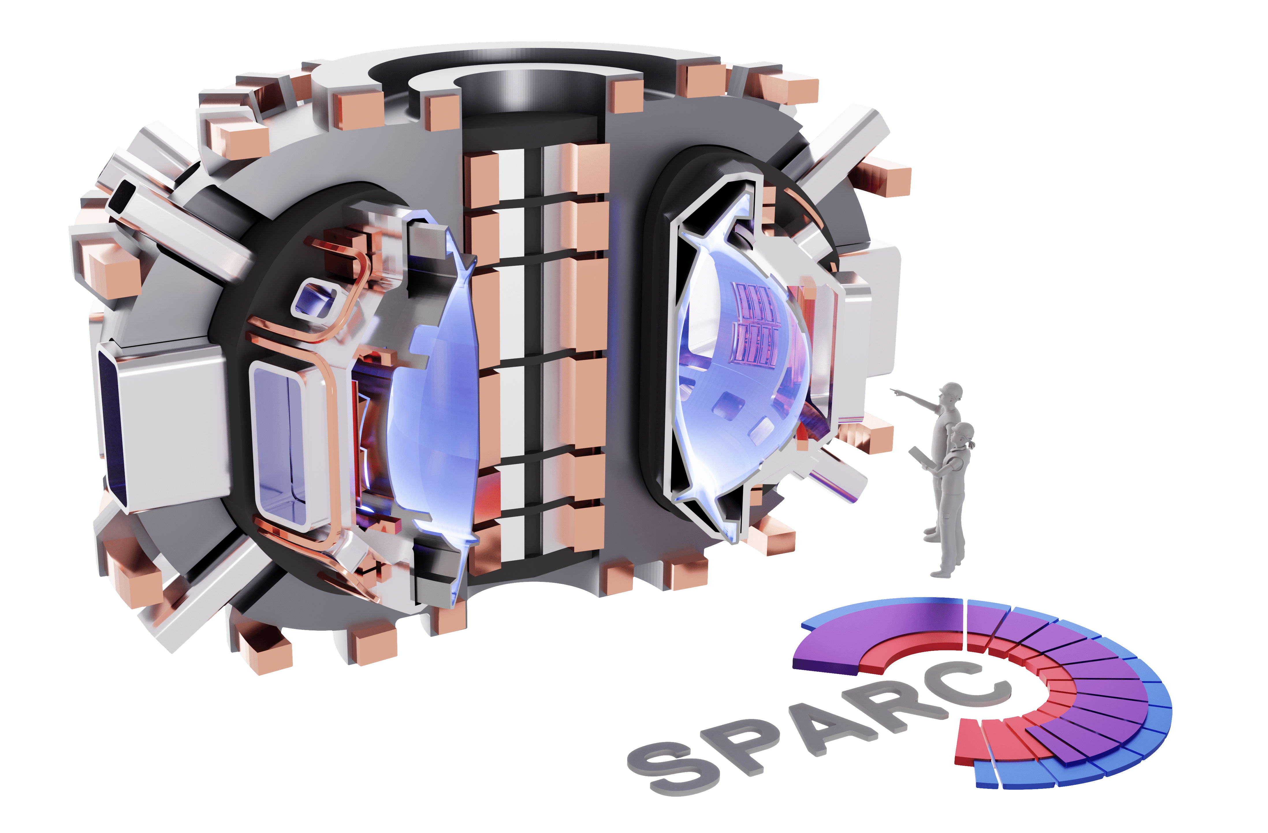
Figure 4. SPARC, the upcoming proof-of-concept tokamak being built by CFS.
The plasma inside has a toroidal current flowing through it for stability and, at times, control of the current can be lost and lead to a disruption event. These events can produce large forces that need to be accounted for in the overarching design. Transient electricity and magnetism simulations have been undertaken to ensure that the materials CFS employ here can handle these disruptions.
During this part of the talk, Brunner discussed a few simulations that were performed at MIT when conducting the Advanced Divertor eXperiment (ADX). This experiment featured a vacuum vessel design that was a predecessor to the company’s current tokamak designs, where COMSOL Multiphysics® was used to study the time-varying magnetic fields and resulting forces, stresses, and displacements on the vessel design. (Read more about this work here.)
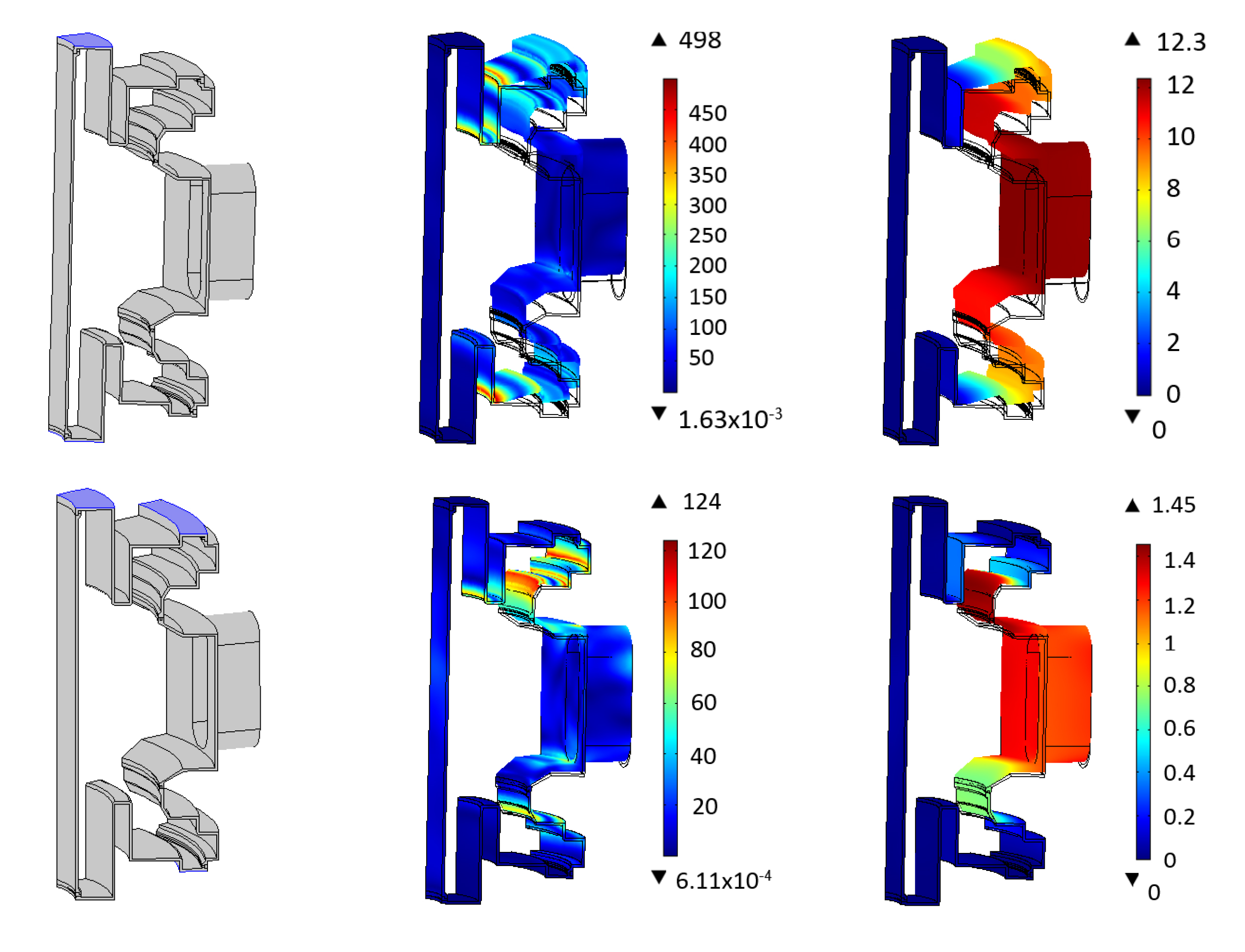
Figure 5. At top, the geometry for the structural model of the ADX shows purple boundaries where the structure is fixed. Stress and displacement simulation results indicate the design requires reinforcement. At bottom, the model geometry shows an additional fixed boundary corresponding to a support block added to the ADX design. Image courtesy of CFS.
Moving Toward Commercial Fusion Energy with Simulation
Progress brings new challenges to overcome. CFS point to superconducting magnets as the key to the future of magnetic fusion, but have found plenty of design areas where optimization is needed. While each example has been possible to model within the COMSOL Multiphysics software, it can be computationally demanding and this is where creativity and software development has come into play.
The IT team at CFS set up multiple Amazon Web Services (AWS) HPC6as to distribute solving. This has permitted the team to scale up their capacity both vertically and horizontally, resulting in more jobs being able to be performed at once and more CPUs can be used per job on more than 50,000 cores. This is possible due to the floating network license that CFS holds with COMSOL and has made the intensely complex fusion simulations much less daunting. “It has reduced our simulation time and costs by at least 50 percent and that allows for faster execution. It has also allowed us to make decisions on time scales that matter for the work that we are doing,” said Brunner.
Next Step
Watch the recorded keynote presentation from CFS to learn more about the challenging process of fusion and the developments they are making in the field.


Comments (0)