
Since their development in the 1960s, subminiature version A (SMA) connectors have become a staple in the RF and microwave industries. The use of these connectors is so widespread, they might even be the most popular RF and microwave connector systems on Earth. To evaluate the performance of an SMA connector, engineers can use the COMSOL Multiphysics® software.
Taking a Look at SMA Connectors with Simulation
SMA connectors are used for a variety of applications, including cellphone antennas and printed circuit board (PCB) testing. To ensure that SMA connectors perform well when used for these and other applications, it’s important for engineers to evaluate their designs.
One option for studying these connectors is with full-wave electromagnetics simulation. This process is made easier when using the RF Module, an add-on to COMSOL Multiphysics, as it includes three parameterized types of SMA connector geometries (4-hole, 2-hole, and vertical mount) in the Part Libraries to enhance the modeling experience.
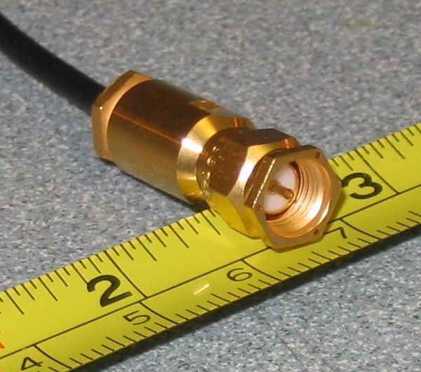
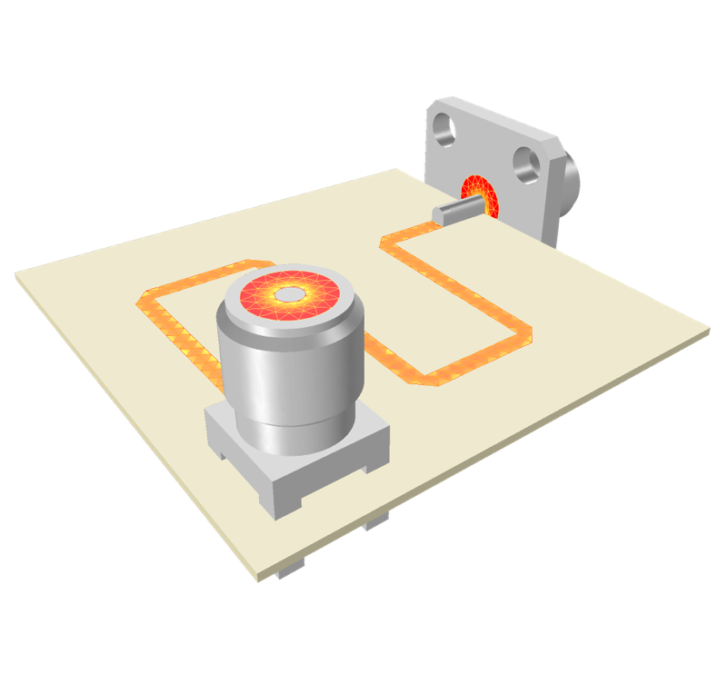
Left: Photograph of an SMA connector. Image by Meggar. Licensed under CC BY-SA 3.0, via Wikimedia Commons. Right: Model of a four-hole and vertical-mount SMA connector. The connectors are linked via a 50-Ω meander microstrip line.
Analyzing an SMA Connector with the RF Module
The example highlighted here examines an SMA connector located on a grounded coplanar waveguide (GCPW). Coplanar waveguides are often found in microwave circuits and can be fabricated on PCBs, which are used in almost all modern electronic devices. Here, the SMA connector is soldered onto one end of a GCPW line and a lumped port terminates the opposite end of the line with 50 Ω.
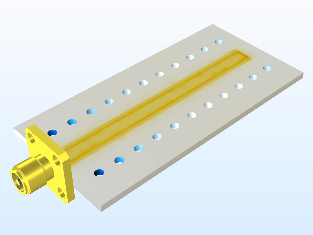
SMA connector geometry.
This model has two main goals. The first is to study how a signal from a coaxial cable travels through an SMA connector and excites a GCPW. The signal is carried through the coaxial cable by a TEM mode at 1 GHz. The electric field of this TEM mode is pointed radially between the inner and outer conductors within the cable. After moving through the cable, the signal travels through the connector and eventually excites the symmetric mode of the GCPW. Depending on the phase, the symmetric electric field in the GCPW either points from the center conductor to the outer conductors or vice versa.
The second goal is to model the 50-Ω passive termination of the GCPW using a lumped port and air bridge. It’s possible to study this passive termination using three different approaches:
- Horizontal configuration, where a lumped port extends from the center to the outer GCPW conductors
- Vertical configuration, where a lumped port extends from the center conductor to an air bridge located above the substrate (the air bridge connects the outer conductors while keeping an air gap between itself and the center conductor)
- Multielement configuration, where a multielement uniform lumped port is used to terminate
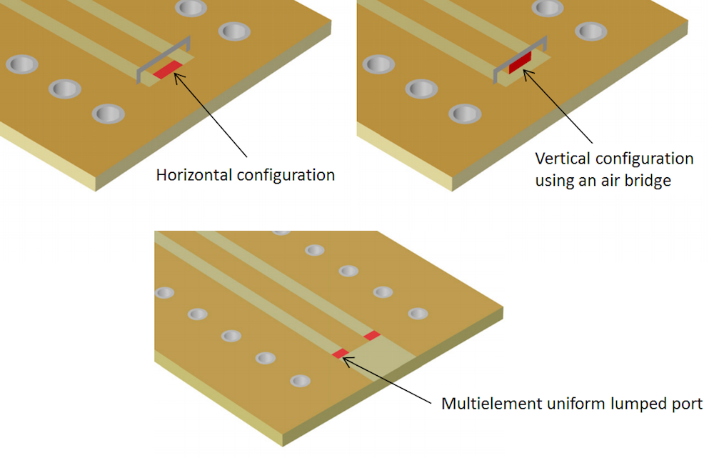
Three methods for adding a port onto a GCPW.
Examining the Simulation Results
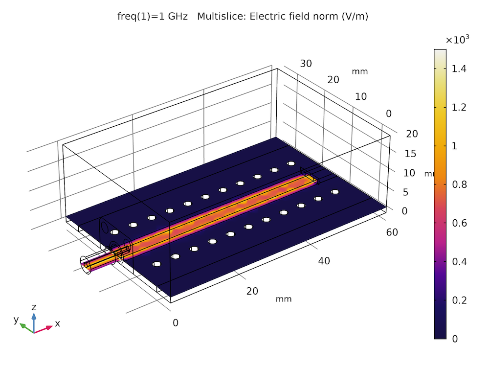
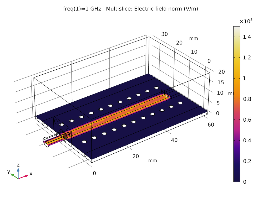
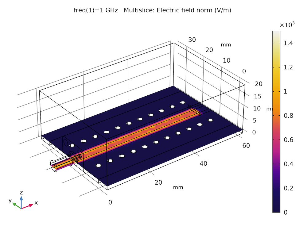
Through the electromagnetics analysis, you can find the norm of the electric field on the top surface of the GCPW circuit, as shown in the images below. Please note that the results here have been adjusted to emphasize the field confined within the ground plane of the GCPW.
Electric field norm plots for the SMA connector. All three configurations match approximately well to the 50-Ω reference impedance, and no standing wave due to reflection is observed.
Since the electric field norm plots do not provide all of the necessary information for this study, it’s also helpful to evaluate the S-parameters for the design. In this case, the results indicate that the passive termination methods have S-parameters (S11) of around -24 dB. With this knowledge, you can evaluate the performance of SMA connectors and improve their designs.
Next Steps
You can try the SMA Connector on a Grounded Coplanar Waveguide tutorial by clicking the button below.
Additional Resources
- Check out these related blog posts:



Comments (0)