
As a nuclear engineer, I’ve attended many thermal engineering classes. Whereas I’ve enjoyed learning techniques to enhance heat transfer, I’ve also found fascinating those applications where it is important to reduce heat transfer using the right choice and combination of materials and shapes. The design of this is vital for many industries, including the building and aerospace industries. Lately, I came across an interesting example of thermal insulation in the most mundane of these things: clothing design. I had to buy a wetsuit and couldn’t resist the temptation to simulate and understand its thermal insulation properties.
Wetsuits and Foamed Neoprene
Modern wetsuits are made of neoprene, and they don’t actually prevent us from getting wet — instead, they are designed to keep us warm. If a wetsuit is tight enough, the layer of water that fills the gap between the wetsuit and our skin will be so thin that it will readily be warmed up by our body heat. After the initial chill, the insulation offered by the foam neoprene allows us to swim and enjoy the water without experiencing its true temperature. In order to maintain its thermal insulation properties while in use, wetsuits are designed to prevent what is called flushing — or cold water entering the wetsuit through the ankles, wrists, and neck.
Why does foamed neoprene offer such good thermal insulation? Foamed neoprene contains small bubbles of nitrogen gas. The presence of such a gas with a very low thermal conductivity reduces heat transfer by almost an order of magnitude, compared to having the skin directly in contact with water. In addition to its favorable thermal properties, there are almost no convection currents in a gas trapped in such tiny bubbles. Heat transport in foamed neoprene occurs mainly through diffusion, a slow transport mechanism that reduces heat loss from our body.
Thermal Insulation: Simulation Confirms Bubbles are Better
To build my model I used COMSOL Multiphysics and the Heat Transfer Module, and considered a 2D domain made with the following layers, from left to right:
| Material | Thickness/Diameter | Thermal Properties |
|---|---|---|
| Skin | 2 mm | Same as water |
| Water | 0.5 mm | Temperature dependent, taken from the Material Library available in COMSOL Multiphysics |
| Comfortable fabric (nylon) | 0.2 mm | Same as above |
| Titanium metal oxide | 0.05 mm | Same as above |
| Neoprene | 3 mm | Same as above |
| Nitrogen bubbles | 0.025 mm | Same as above |
| Resistant fabric (nylon) | 0.2 mm | Same as above |
The values provided in the table above are based on data that I found in an online search. If needed, or if I come across new information or specifications, I can test different materials and geometrical properties with just a few clicks. Additionally, my model is fully parameterized. That’s one of the main advantages of simulation — it enables the verification and optimization of a design right on the computer, before launching an expensive experimental campaign. The model geometry is depicted below, in Figure 1.
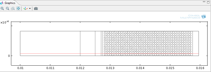
Figure 1: Foamed neoprene model geometry with postprocessing cut line (in red).
Boundary conditions and initial temperature used in the model are summarized below:
| Body Heat Flux, left boundary | Sea Temperature, right boundary | Initial Temperature, all domains | 100 W/2 m2 (Ref. 2 and 3) | 17.2°C (Ref. 4, September) | 36.1°C (Ref. 5) |
|---|
The simulation results shown in Figure 2 confirm that having a foamed neoprene wetsuit, with the nitrogen bubble insulation, is a good choice, especially if we’re in cold water for more than five minutes. We have three minutes more before we reach a skin temperature of 24°C, with respect to a non-foamed neoprene wetsuit.
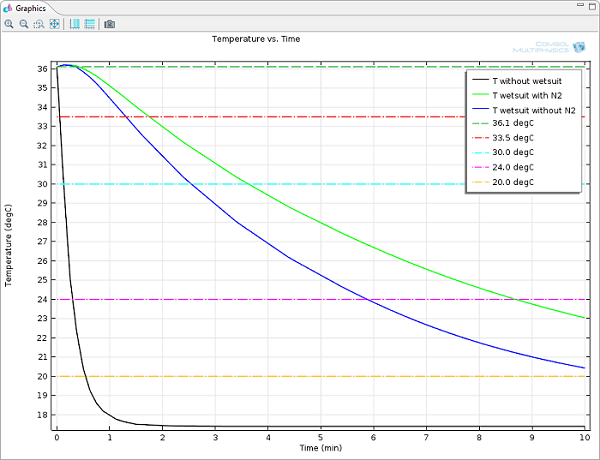
Figure 2. Skin temperature vs. time.
Figures 3 and 4 provide more details about the temperature profile along a horizontal cut line and the temperature distribution across the whole simulation domain, respectively.
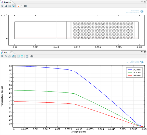
Figure 3. From top to bottom: model geometry with postprocessing cut line (in red); temperature values along the cut line at t= 2, 6, and 9 min.
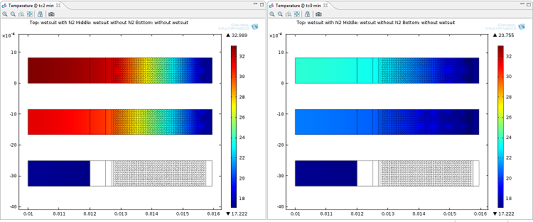
Figure 4. Temperature distribution at t=2 minutes (left) and 9 minutes (right).
Heat Transfer Modeling Tips
I’m sure you noticed in Figure 1 that I’ve actually drawn in the nitrogen bubbles. It would also have been possible to have simulated the bubbles by applying the technique for simulating Homogenized Pore Scale Flow and Thermal Conduction, which describes how to represent the bubbles with their equivalent volume-averaged thermal properties, allowing them to be simulated without drawing them or losing too much in accuracy. I could have simulated them without individually drawing all the domains thanks to boundary conditions in COMSOL that are specifically designed to model domains that are geometrically much smaller than the rest of the model. See Figures 5, 6, and 7 for more details about the options available in the Heat Transfer Module.
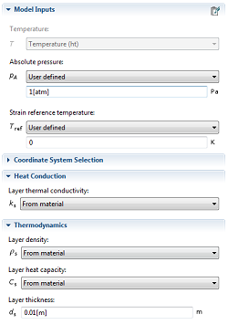
Figure 5. Highly Conductive Layer boundary condition (click to enlarge).
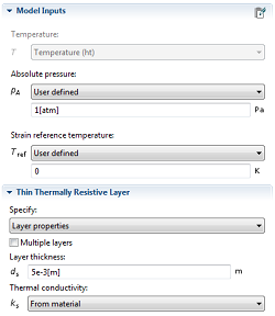
Figure 6. Thin Thermally Resistive Layer boundary condition (click to enlarge).
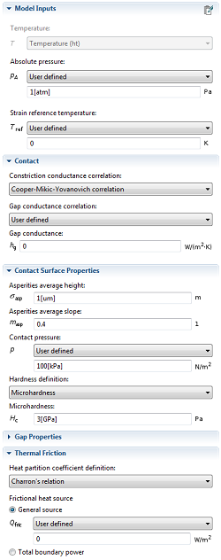
Figure 7. Thermal Contact boundary condition (click to enlarge).
Additional Resources
When creating the model, I used some of the following resources in order to set up the model and select the model properties:
- Homogenized Pore Scale Flow and Thermal Conduction functionality in COMSOL, which allows for the use of image data to represent 2D material distributions and use the image’s color or gray scale to identify regions with different materials
- Thermoregulation, a resource about how the body regulates its heat output power
- Skin description
- Boston’s average water temperature
- Hypothermia


Comments (7)
Jeffrey Moran
June 3, 2016Would it be possible to make the MPH file for this model available? Thank you!
Valerio Marra
June 6, 2016Hi Jeffrey,
Unfortunately, I don’t have the model anymore but you can start from here https://www.comsol.com/model/silica-glass-block-coated-with-a-copper-layer-452 to familiarize with the physics at hand and the capabilities of the COMSOL Multiphysics® software.
You can then use the values and conditions discussed in the blog post to reproduce the model, it should be fairly easy.
Let me know if you need anything else and as usual, please contact support@comsol.com if you have any technical questions.
Best regards,
Valerio
Jeffrey Moran
June 6, 2016As it turns out, I don’t have the Heat Transfer Module, so I can’t use the Thin Layer feature with the “Conductive” option (the only choice is “Resistive”). I should still be able to re-create this model with all of the thin layers meshed, however.
Thanks for your response!
Jeffrey Moran
June 6, 2016Actually, I do have one more question for you. In the blog post you mentioned a feature called “Homogenized Pore Scale Flow and Thermal Conduction.” However, when I clicked on the link it just took me to the models page, and I searched through the entire model library but wasn’t able to find a model demonstrating this feature. Is it possible to obtain an MPH file demonstrating this? Does it require the Heat Transfer module?
Thank you again.
Valerio Marra
June 9, 2016Hi Jeffrey,
Thank you for reporting this.
The application “Image Import: Homogenized Pore Scale Flow and Thermal Conduction” (https://www.comsol.com/model/image-import-homogenized-pore-scale-flow-and-thermal-conduction-12211) should now be available.
Best regards,
Valerio
Jeffrey Moran
June 20, 2016Thank you for your response. I clicked on the link you provided and tried to download the model files. I saw this message:
“Please contact your sales representative or support@comsol.com for the model files.”
Would it be possible to make those models available, or should I email COMSOL support?
Thanks again.
Valerio Marra
June 21, 2016Hi Jeffrey,
I would get in touch with support@comsol.com.
Thank you,
Valerio