Discussion Closed This discussion was created more than 6 months ago and has been closed. To start a new discussion with a link back to this one, click here.

Multiple Rotors in a Fluid

Please login with a confirmed email address before reporting spam

Hello,

I'm new and I'd like to ask for some advice regarding the possibilities of doing a simulation of multiple propellors, with Comsol's CFD bundle.

The project I want to do is very basic. Its a mechanism of 16 rotors that are connected, and placed in a circle. They are driven by an internal motor, and RC controlled. The goal is to see if the whole composition would spin around its axis like a wheel, and move sideways forward through water, like drill.

I have constructed a prototype model, and would also like to make a computer simulation. Click on the links below to see the pictures of the model and designs.

What I would like to know if its possible to simulate the motion of these propellors, and study their behavior in a medium of particles (air / water) with Comsol.

Looking forward to hear from you,

greetings,

m.

--

Clip: youtu.be/VTwqssM8yfE

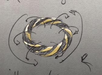
A first rough sketch of the original idea:

www.800million.org/stukken/ring_schets.jpg


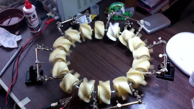
The mechanical model in action:

www.800million.org/stukken/Loop_2.jpg


How it's driven by little motors from the inside:

www.800million.org/stukken/loop_1.jpg


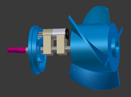
The technical design:

www.800million.org/stukken/geheel.png

www.800million.org/stukken/motor.png

www.800million.org/images/Torus_rotors_circle.jpg


For a CFD simulation a basic setup would be sufficient:

www.800million.org/images/Basic_Rotor.jpg

www.800million.org/images/Ring_basic.jpg


3 Replies Last Post May 26, 2015, 5:39 a.m. EDT

Please login with a confirmed email address before reporting spam

Posted: 1 decade ago Jun 17, 2011, 2:49 a.m. EDT
Hi,

I have been running a vaguely similar project, meaning that I have rotating part coupled with a sliding part but they have a fixed position in space.

First of all, what you want to do is quite a pain in the neck. In order to simulate rotations comsol uses a rotating machinery module that does not allow coupling of rotational movement with traslational movement. I would say that you need to couple CFD and ALE modules. I had to go through support several times so I would suggest you to start with a simple 2D model to start handling the coupling of the two modules in particular regarding the possibility of having a closed volume with no inlet/outlet and having the fluid displaced by the moving rotors.

Two more things, on the cfd side you need to calculate the reynolds number first of all to understand whether your motion will be laminar or turbulent; on the ale side you will need to carefully subdivide the domain around your moving rotors and mesh all those subdomains and assign them 'mesh movements' or 'mesh velocities' so that you may help the solver do its job at deforming the mesh without excessive problems (problems there will be anyway...).

Cheers

Hi, I have been running a vaguely similar project, meaning that I have rotating part coupled with a sliding part but they have a fixed position in space. First of all, what you want to do is quite a pain in the neck. In order to simulate rotations comsol uses a rotating machinery module that does not allow coupling of rotational movement with traslational movement. I would say that you need to couple CFD and ALE modules. I had to go through support several times so I would suggest you to start with a simple 2D model to start handling the coupling of the two modules in particular regarding the possibility of having a closed volume with no inlet/outlet and having the fluid displaced by the moving rotors. Two more things, on the cfd side you need to calculate the reynolds number first of all to understand whether your motion will be laminar or turbulent; on the ale side you will need to carefully subdivide the domain around your moving rotors and mesh all those subdomains and assign them 'mesh movements' or 'mesh velocities' so that you may help the solver do its job at deforming the mesh without excessive problems (problems there will be anyway...). Cheers

Please login with a confirmed email address before reporting spam

Posted: 1 decade ago Jun 17, 2011, 6:00 a.m. EDT
Hi Amir,

Thanks for you reply.

You bring up some interesting points, and there's one new thing that I now realised when you mention to calculate the reynolds number first.

It's not hard to get a simulation going were the 'wheel' would spin round its axis, as each rotor would drill its way forward in any medium. But for the whole wheel to move as a global unit sideways due to 'thrust' generated by the compression in the middle, this is something else. If the density of the medium is too thick or too light nothing will happen. This is something one can intuitively incorporate when building a mechanical model, but easily overlooks when using cfd. I guess every medium must have its 'sweet spot' where the speed of the rotors along with the shape of the rotors, the width of the ring, and the density of the medium, gives the right balance so the whole torus would move steadily forward, having a laminar surrouding flow.

mh, this is indeed far more difficult than I already imagined ... it brings up also the thought of finding out how early helicopter builders found their groove to get the 'perfect' lift, lots of trial and error ...

cheers,

m.

Hi Amir, Thanks for you reply. You bring up some interesting points, and there's one new thing that I now realised when you mention to calculate the reynolds number first. It's not hard to get a simulation going were the 'wheel' would spin round its axis, as each rotor would drill its way forward in any medium. But for the whole wheel to move as a global unit sideways due to 'thrust' generated by the compression in the middle, this is something else. If the density of the medium is too thick or too light nothing will happen. This is something one can intuitively incorporate when building a mechanical model, but easily overlooks when using cfd. I guess every medium must have its 'sweet spot' where the speed of the rotors along with the shape of the rotors, the width of the ring, and the density of the medium, gives the right balance so the whole torus would move steadily forward, having a laminar surrouding flow. mh, this is indeed far more difficult than I already imagined ... it brings up also the thought of finding out how early helicopter builders found their groove to get the 'perfect' lift, lots of trial and error ... cheers, m.

Please login with a confirmed email address before reporting spam

Posted: 9 years ago May 26, 2015, 5:39 a.m. EDT
Hi

I am also working on the same problem but i am getting some errors.
Let me know whether you ended up with solution ?
If so i will post my queries

With Regards

J.Bharadwaj
Hi I am also working on the same problem but i am getting some errors. Let me know whether you ended up with solution ? If so i will post my queries With Regards J.Bharadwaj

Note that while COMSOL employees may participate in the discussion forum, COMSOL® software users who are on-subscription should submit their questions via the Support Center for a more comprehensive response from the Technical Support team.