The Application Gallery features COMSOL Multiphysics® tutorial and demo app files pertinent to the electrical, structural, acoustics, fluid, heat, and chemical disciplines. You can use these examples as a starting point for your own simulation work by downloading the tutorial model or demo app file and its accompanying instructions.
Search for tutorials and apps relevant to your area of expertise via the Quick Search feature. Note that many of the examples featured here can also be accessed via the Application Libraries that are built into the COMSOL Multiphysics® software and available from the File menu.

This tutorial model analysis of a microstrip patch antenna shows how to couple the finite element method (FEM) to the boundary element method (BEM) for evaluating the field outside the FEM computational domain. The model computes the S-parameter, near-field distribution, and far-field ... Read More

A wideband antenna study, such as an S-parameter or far-field pattern analysis, can be obtained by performing a transient response analysis and a time-to-frequency fast Fourier transform (FFT). This model runs a time dependent study first and then transforms the dependent variable, the ... Read More

An axisymmetric 3D structure such as a conical horn antenna can be simulated in a fast and efficient way using only its 2D layout. In this model, the antenna radiation and matching characteristics are computed very quickly with respect to the dominant TE mode from the given circular ... Read More

This app demonstrates the following: Parameterized geometries Visualizing material appearance, color, and texture Multiple plots in the same window to visualize the results Options to visualize the results with different views using check boxes Microstrip patch antenna arrays are ... Read More

This example of a dipole antenna array demonstrates a cost-effective analysis using the Boundary Element Method (BEM). When dealing with a large array made of metallic radiators, the Finite Element Method (FEM) would necessitate greater computational resources. The simulation results ... Read More

This model uses the Semiconductor and RF modules to describe a photoconductive antenna (PCA). A laser pulse is applied on the surface of undoped LT-GaAs to generate electron-hole-pairs, which move under the influence of an external E-field creating a transient electric current pulse. ... Read More

A radome minimizes losses and improves radiation characteristics of an antenna through its design. The structure can be optimized to minimize the transmission loss and also designed to improve radiation characteristics including antenna directivity and side lobes. Shown in the model is ... Read More

This model addresses the concept of wireless power transfer by studying the energy coupling between two circular loop antennas tuned for UHF RFID frequency whose size is reduced using chip inductors. The circular loop antenna provides inherent inductive coupling by its shape, and it can ... Read More
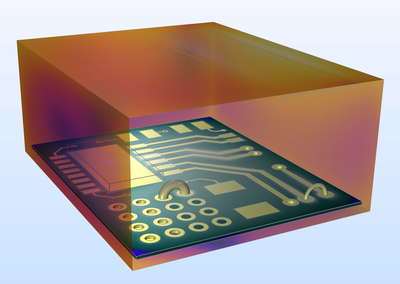
This example provides a walkthrough on how to simulate the basic radiated emission of a printed circuit board and its immunity response from outside noise. First, when one of the microstrip lines is excited, the crosstalk to an adjacent printed line and the radiated field, through an ... Read More

Feeding antennas with proper signals can be difficult. The signal is often described as a voltage, and voltages are not well defined in electromagnetic wave formulations. There are several tricks to model voltage generators in such situations, and one is the magnetic frill. This model ... Read More