Design Module

Build Geometries and Modify Imported Files in COMSOL Multiphysics®

When running a simulation, it is important to use the best geometric model for the planned analysis. The Design Module expands the CAD functionality of COMSOL Multiphysics® with additional tools for importing and revising existing CAD models, as well as sketching and building geometries from the ground up.

Whether removing irrelevant details from an existing geometry, editing and reparameterizing certain features of an imported CAD model, or constructing parametric geometries, the Design Module has specialized features and functionality or preparing a model for analysis.

Contact COMSOL
A metallic geometry of a car disc brake made up of a ventilated disc and caliper assembly.

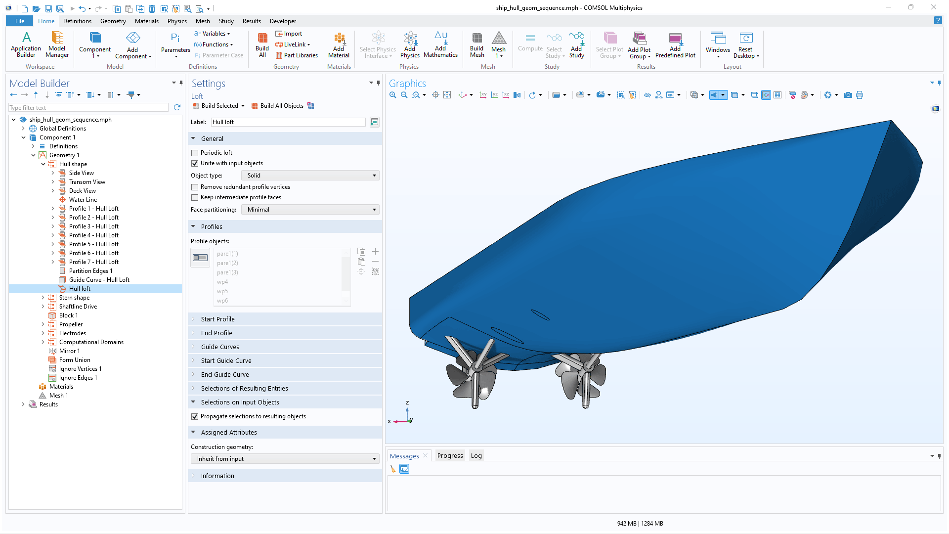
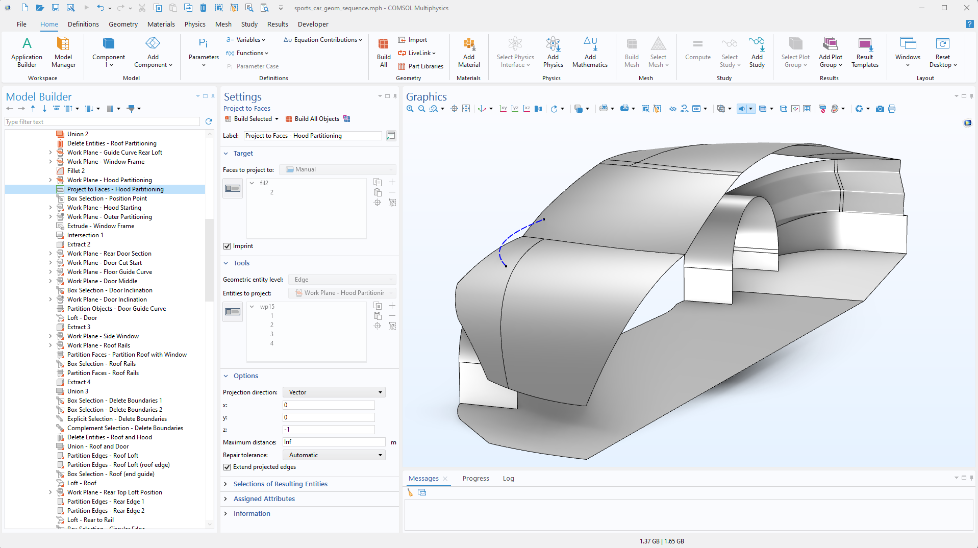
Constraints and Dimensions

The Design Module includes a set of sketching tools used for adding constraints and dimensions to planar drawings for 2D models, 3D work planes, and in geometry parts. Some of the available constraint options include parallel, perpendicular, and tangent constraints. For example, to make two polygon segments meet at 90 degrees, the two edges are clicked and perpendicular constraint is used. The options for dimensions include, among others, length dimension, radius, and angle. Interactively setting a length dimension, for example, is as simple as clicking and dragging an edge. To aid in creating consistent drawings, the Design Module provides immediate feedback, whether a sketch is underdefined, overdefined, or well defined.

All of the dimensions detailed above can be made parametric using the general parametric framework in COMSOL Multiphysics®. This makes it possible to run parametric sweeps across one or multiple dimensions. Additionally, when combined with the Optimization Module, parametric optimizations can be performed.

CAD Import Functionality

The Design Module contains all of the functionality of the CAD Import Module, which is used for importing and exporting a wide range of CAD file formats. To ensure the validity of the imported geometric information, a CAD model can be automatically or manually repaired and defeatured to assist with setting up and running analysis. This functionality extends to associative geometry import, where the software reads information in the CAD file to identify geometric entities and compare them with a previously imported version of the file. This allows physics and other settings on the geometry to be retained as much as possible. For more details on these features, see the CAD Import Module page.

In addition, the Design Module is especially well suited for importing CAD assemblies that often contain small gaps and overlaps between components. These can be collapsed using advanced Boolean operations, which are exclusive to the Design Module. These operations are utilized by the automatic geometry cleanup functionality when generating the geometric model for simulation but can also be applied manually.

Geometric Operations in the Design Module

The Design Module offers functionality for creating and modifying geometry as well as more advanced Boolean operations.

A closeup view of the Fillet operation settings and a bracket model in the Graphics window.

Fillet

In structural mechanics, fillets are used to reduce stress concentrations, while in electromagnetics, they help prevent electric breakdown. Using the Design Module, fillets are created by simply selecting one or more edges and specifying a radius or width to round the corners of the selected edges. The variable radius option allows different radius values along the filleted edge, creating a smoother transition between faces for improved aesthetics—an important consideration in applications such as consumer electronics. Using a gradually changing radius can also help resolve space constraints, making it easier to design components that need to fit within tight spaces.

A close-up view of the Model Builder with the Offset Faces node highlighted and a brake caliper model in the Graphics window.

Offset Faces

The Offset Faces operation is used to offset faces on 3D geometry objects along their normal direction. This feature is also useful for editing 3D geometries and enables the parameterization of geometric features in objects imported from 3D CAD files. In MEMS applications, this operation can be used to create 3D geometries in a way that emulates the deposition of materials onto nonflat surfaces.

A closeup view of the Model Builder with the Midsurface node highlighted and a model of a ladder frame for a truck in the Graphics window.

Midsurface

The Midsurface operation removes the thickness of a solid object having constant thickness, resulting in a surface object. Such surface objects are typically used with a Shell interface, where the thickness is represented as a physics property instead of a geometric feature.

A closeup view of the Model Builder with the Loft node highlighted and a ship hull model in the Graphics window.

Loft

The Loft operation enables the creation of a lofted surface using specified profile and guide curves. This surface is formed from one or several faces that interpolate between the profiles. The operation is particularly useful for generating smooth geometric transitions among profile curves with varying shapes.

A close-up view of the Model Builder and a mounting bracket model in the Graphics window.

Chamfer

Chamfers are created by simply clicking on an edge and specifying a distance. This will create beveled corners at the selected edges.

A close-up view of the Model Builder with the Transform Faces node highlighted and an enclosure model in the Graphics window.

Transform Faces

The Transform Faces operation applies a linear transformation to selected faces on 3D geometry objects. This transformation can include displacement, rotation, and isotropic scaling. Its functionality becomes particularly useful when working with models imported from 3D CAD files. For example, the operation allows for the parameterization of geometric features in imported objects, sweeps over parameters, and the optimization of designs when used with the Optimization Module.

A closeup view of the Model Builder with the Thicken node highlighted and an industrial fan model in the Graphics window.

Thicken

The Thicken operation is used to convert a surface object to a solid object by giving it a thickness, usually in the normal direction.

A close-up view of the Project to Faces node Settings window and a sports car model in the Graphics window.

Project to Faces

The Project to Faces operation projects edges onto faces to create imprints, enabling patterns to be applied to curved surfaces. The projection can be performed normal to the target faces or along a user-defined direction.

A closeup view of the Geometry settings and a turbine model in the Graphics window.

Advanced Boolean Operations

The Design Module provides advanced Boolean operations designed to handle more complex geometry models with greater accuracy. These operations are particularly useful when computing the union of objects with touching faces that do not match exactly. They are also effective for collapsing gaps and overlaps that fall within a specified tolerance.

Every business and every simulation need is different.

In order to fully evaluate whether or not the COMSOL Multiphysics® software will meet your requirements, you need to contact us. By talking to one of our sales representatives, you will get personalized recommendations and fully documented examples to help you get the most out of your evaluation and guide you to choose the best license option to suit your needs.

Just click on the "Contact COMSOL" button, fill in your contact details and any specific comments or questions, and submit. You will receive a response from a sales representative within one business day.

Next Step

Request a Software Demonstration