Microfluidics Module

Perform Multiphysics Simulations of Microfluidic Devices

The Microfluidics Module, an add-on to COMSOL Multiphysics®, provides easily operated features for studying microfluidic devices. Important applications include simulations of lab-on-a-chip devices, digital microfluidics, electrokinetic and magnetokinetic devices, and inkjets. The Microfluidics Module can be used for simulating creeping, laminar, porous media, multiphase, and slip flow, and it can solve stationary and time-dependent flows in 2D and 3D. When combined with other modules from the COMSOL product suite, the module's functionality for modeling multiphysics phenomena can be expanded to model fluid–structure interaction, thermal flows, and more.

Contact COMSOL
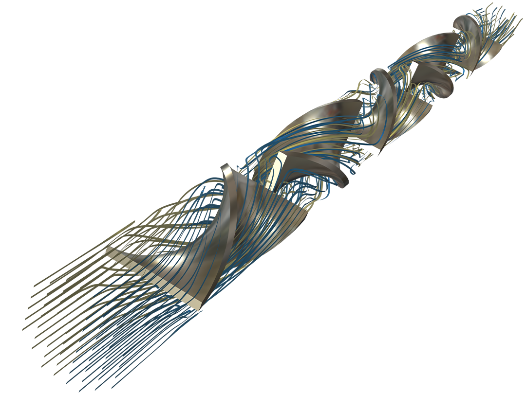
A split-and-recombine mixer channel model showing the concentration.

Describe Fluids at the Microscale

Microfluidic flows occur on length scales that are orders of magnitude smaller than macroscopic flows. Manipulation of fluids at the microscale has a number of advantages; because they are smaller, microfluidic systems typically operate faster and require less fluid than their macroscopic equivalents.

Energy inputs and outputs (for example, heat generated in a chemical reaction) are also easier to control because the surface-to-area volume ratio of the system is much greater than that of a macroscopic system. In general, as the length scale of the fluid flow is reduced, properties that scale with the surface area of the system become comparatively more important than those that scale with the volume of the flow.

The Microfluidics Module is designed specifically for handling momentum, heat, and mass transport with special considerations for fluid flow at the microscale.

What You Can Model with the Microfluidics Module

Perform various microfluidics analyses with the COMSOL® software.

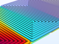
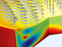
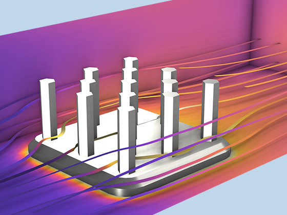
A close-up view of a rectangular model with rainbow contours.

Lab-on-a-Chip Devices

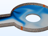
Compute the radial pressure distribution and flow rate through a rotating lab-on-a-chip platform.

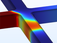
A close-up view of a microchannel model showing the velocity field.

Microfluidic Channels

Infuse and flush connected pieces of equipment with a fluid.

A close-up view of a micropump model showing the velocity field.

Micropumps

Model microfluidic systems with applications ranging from biological fluid handling to microelectronic cooling.

A close-up view of a micromixer model showing the concentration.

Micromixers

Simulate rapid mixing of different fluid streams.

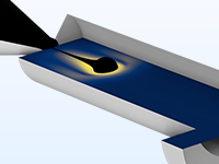
A close-up view of an inkjet model showing the velocity magnitude.

Inkjet Printing

Model the fluid flow in an inkjet to predict optimal inkjet design.

A close-up view of a drug delivery device model showing the concentration.

Drug Delivery

Describe the operation of a drug delivery system.

A close-up view of a fuel cell model showing the relative humidity.

Fuel Cells

Study proton exchange membrane (PEM) fuel cell designs and construction challenges.

A close-up view of an electrowetting lens model showing the velocity magnitude.

Electrowetting Optical Devices

Modify a contact angle by changing the voltage applied to the conducting liquid.

A close-up view of an electrokinetic valve model showing the concentration.

Electrokinetic Valves

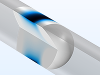
Analyze pressure-driven flow and electrophoresis in a 3D microchannel system.

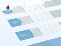
A close-up view of four detection tests with a liquid sample.

Detection Tests

Study possible symmetries in the spreading of a liquid sample in a test strip.

Features and Functionality in the Microfluidics Module

The capabilities of the Microfluidics Module can address multiple simulation problems.

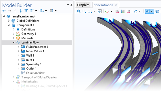
A close-up view of the Model Builder with the Laminar Flow node highlighted and a lamella mixer in the Graphics window.

Single-Phase Flow

The Fluid Flow interfaces use physical quantities, such as pressure and flow rate, and physical properties, such as viscosity and density, to define a fluid flow problem. The Laminar Flow interface covers incompressible and weakly compressible flows. This interface also allows for the simulation of non-Newtonian fluid flow. An interface for creeping flow is used when the Reynolds number is significantly smaller than one. This is often referred to as Stokes flow and is appropriate for use when viscous flow is dominant. It is usually applicable to microfluidic devices.

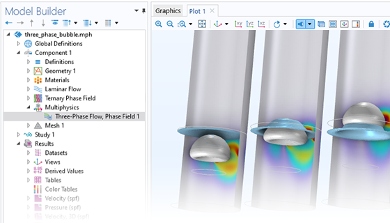
A close-up view of the Model Builder with the Three-Phase Flow, Phase Field node highlighted and a three-phase bubble model in the Graphics window.

Three-Phase Flow

The Laminar Three-Phase Flow, Phase Field multiphysics interface is designed to track the interfaces between three immiscible and incompressible fluids. The flow is assumed to be laminar; that is, the Reynolds number is low to moderate, and the density of each phase is constant. The interface solves the Navier–Stokes equations for the conservation of momentum as well as a continuity equation for the conservation of mass. The interface position is tracked by solving four additional transport equations, two for the phase field variables and two for the generalized chemical potentials. The movement of the surface is determined by the minimization of free energy. A Ternary Phase Field interface is also available for tracking moving interfaces between three immiscible fluids by solving for two phase field variables and two generalized chemical potential variables.

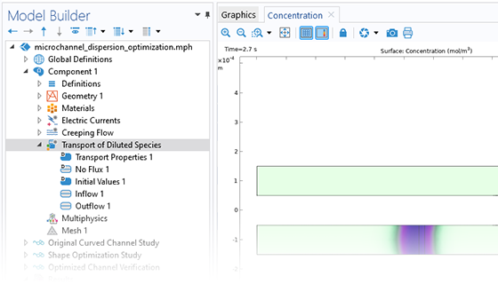
A close-up view of the Model Builder with the Transport of Diluted Species node highlighted and a microchannel model in the Graphics window.

Transport of Species

The Microfluidics Module provides a dedicated interface for transport of diluted species. It is used to simulate chemical species transport through diffusion, convection (when coupled with fluid flow), and migration in electric fields for mixtures where one component — a solvent — is present in excess (90 mol% or greater). It is typically employed to model the performance of mixers. For modeling chemical reactions in microfluidic devices, the Microfluidics Module can be combined with the Chemical Reaction Engineering Module, which also makes available transport of concentrated species with binary diffusion.

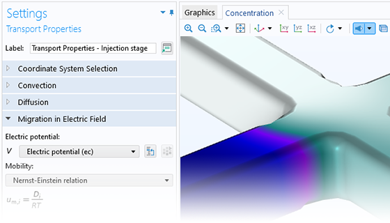
A close-up view of the Transport Properties settings and an electrokinetic valve model in the Graphics window.

Electrokinetic Flow

When modeling the transport of diluted species, the electromigration of ions in a static electric field can be included according to the Nernst–Planck equation. Applications of this functionality include electrophoretic mobility and electroosmotic flow, i.e., electrokinetic flow. The Microfluidics Module can be combined with the Chemical Reaction Engineering Module to access the Nernst–Planck interface and Electrophoretic Transport interface, which are dedicated to the modeling of electrolytes and can include the formulations of Poisson’s equation or the electroneutrality condition for the charge balance. The combination of Nernst–Planck and Poisson's equations can be used for modeling charged double layers and electroosmotic flow.

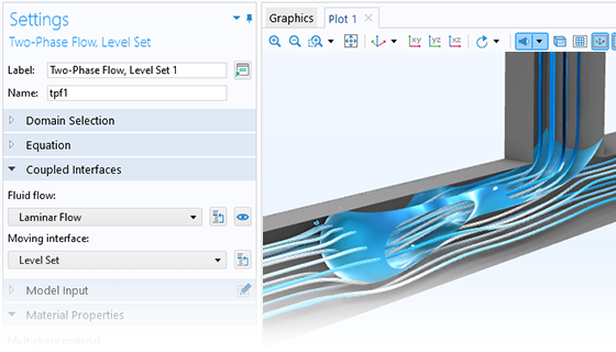
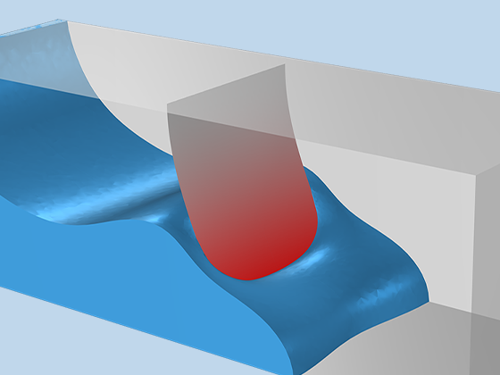
A close-up view of the Two-Phase Flow, Level Set node settings and a droplet breakup model in the Graphics window.

Two-Phase Flow

Three different methods are available in the Microfluidics Module for modeling two-phase flow: level set, phase field, and moving mesh methods. These are used to model two fluids separated by a moving fluid interface, where the interface is tracked in detail, including surface curvature and surface tension forces. The level set and phase field methods use a fixed background mesh and solve additional equations to track the interface location. The moving mesh method solves the flow equation on a moving mesh, and boundary conditions representing the fluid interface are directly applied at the surface. In this case, additional equations are solved for the mesh deformation by means of the arbitrary Lagrangian–Eulerian (ALE) method. All of these methods and their interfaces support both compressible and incompressible laminar flows, where one or both fluids can be non-Newtonian.

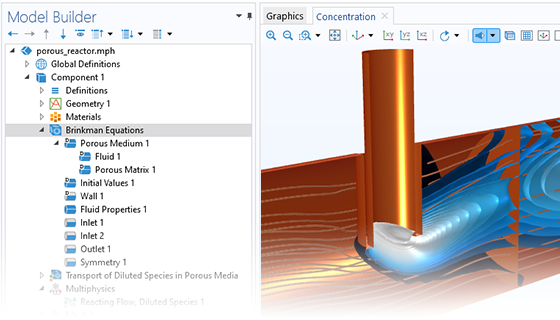
A close-up view of the Model Builder with the Brinkman Equations node highlighted and a porous reactor model in the Graphics window.

Porous Media Flow

Porous media flow can also occur in microscale geometries. When the pore size is in the micron range, the flow is often friction-dominated; in such cases, Darcy’s law can be used to solve the flow. The Microfluidics Module features a dedicated interface for porous media flow based on Darcy's law. In this case, shear stresses perpendicular to the flow are neglected. For intermediate flows, an interface for the Brinkman equations is available. This interface models flow through a porous medium where shear stresses cannot be neglected. There is support for both the Stokes–Brinkman formulation, suitable for very low flow velocities, and Forchheimer drag, which is used to account for effects at higher velocities. The fluid can either be incompressible or compressible, provided that the Mach number is less than 0.3. The formulation allows for free and porous media models, including porous media using the Brinkman equations or laminar flow.

These interfaces are appropriate for microfluidic porous media flow. Example applications include paper microfluidics and transport in biological tissue.

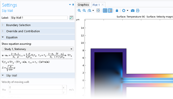
A close-up view of the Slip Wall settings and a benchmark model in the Graphics window.

Rarefied and Slip Flow

Rarefied gas flow occurs when the mean free path of the molecules becomes comparable with the length scale of the flow. The Knudsen number, Kn, characterizes the importance of rarefaction effects on the flow. As the gas becomes more rarefied (corresponding to how high the Knudsen number is), the Knudsen layer — which is present within one mean free path of the wall — begins to have a significant effect on the flow. For Knudsen numbers below 0.01, rarefaction can be neglected, and the laminar flow interfaces of the Microfluidics Module can be used with nonslip boundary conditions. For slightly rarefied gases (0.01 < Kn < 0.1), the Knudsen layer can be modeled by appropriate boundary conditions at the walls together with the continuum Navier–Stokes equations in the domain. In this instance, a Slip Flow interface is available in the Microfluidics Module. To model higher Knudsen numbers, the Molecular Flow Module is required.

Expand Your Modeling with the Microfluidics Module

As with the other products in the COMSOL product suite, when the Microfluidics Module is added to COMSOL Multiphysics®, the features and functionality are fully integrated into the modeling workflow and are ready to be used with other modules. For instance, the Microfluidics Module can be combined with the:

  • Heat Transfer Module to model thermal flows as well as conduction, natural and forced convection, Joule heating, thermophoresis, and Marangoni effects
  • AC/DC Module to study the effects of magnetophoresis and magnetohydrodynamics
  • Structural Mechanics Module to perform fluid–structure interaction simulations for fixed and deforming geometries with single-phase or multiphase flow
  • Chemical Reaction Engineering Module to model chemical reactions and transport of concentrated species and to access advanced capabilities for modeling transport of electrolytes and ions with electric fields as driving forces

Every business and every simulation need is different.

In order to fully evaluate whether or not the COMSOL Multiphysics® software will meet your requirements, you need to contact us. By talking to one of our sales representatives, you will get personalized recommendations and fully documented examples to help you get the most out of your evaluation and guide you to choose the best license option to suit your needs.

Just click on the "Contact COMSOL" button, fill in your contact details and any specific comments or questions, and submit. You will receive a response from a sales representative within one business day.

Next Step

Request a Software Demonstration