
The boundary element method (BEM) is included in the Acoustics Module as a physics interface. This interface, available as of version 5.3a of the COMSOL Multiphysics® software, can be seamlessly combined with interfaces based on the finite element method (FEM) to model, for example, acoustic-structure interaction problems. This functionality expands the range of problems that can be solved with the Acoustics Module. Here, we look into the BEM functionality, examples, and BEM-specific postprocessing.
The Advantages of BEM for Acoustics Modeling
BEM functionality is available in the Acoustics Module as the Pressure Acoustics, Boundary Elements interface. The interface can solve 2D and 3D acoustics problems that have constant-valued material properties within each domain. The fluid model can include dissipation by using complex-valued material data. Furthermore, the BEM interface’s implementation as a scattered field formulation means that it can handle scattering problems (see the image below). As we will see below, the introduction of BEM allows users to solve a new category of problems that were not possible before.
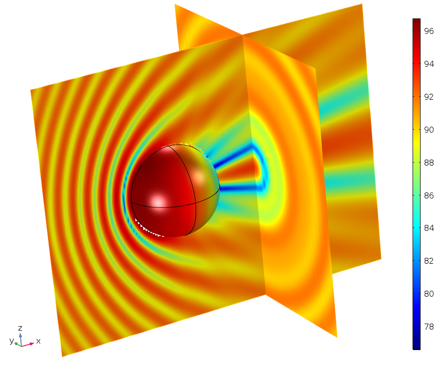
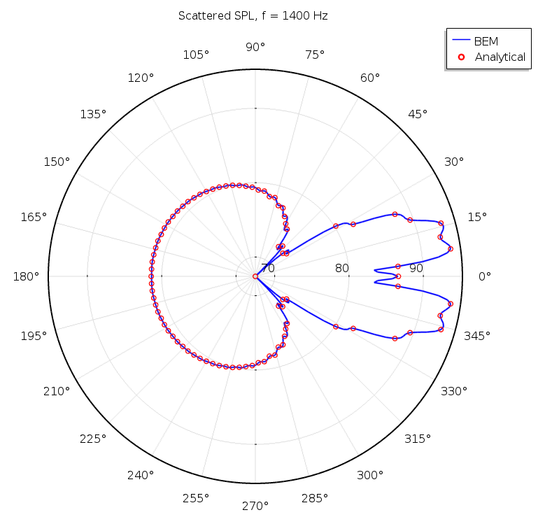
Classical BEM benchmark model of a spherical scatterer for which the results are compared to an analytical solution. The left image shows the sound pressure level in two cut planes at 500 Hz, while the right image shows a comparison of the scattered field at 1400 Hz. Images from the Spherical Scatterer: BEM Benchmark tutorial model.
An important feature is the ability to couple the BEM-based interface with FEM-based interfaces. For example, by using the Acoustic-Structure Boundary multiphysics coupling feature, you can couple the acoustics BEM interface to vibrating structures based on FEM. In addition, BEM and FEM acoustic domains can be combined by using the Acoustic BEM-FEM Boundary multiphysics coupling.
This flexibility allows BEM and FEM to be used where they are best suited and this is all done within the same user interface, as with all other physics couplings in COMSOL Multiphysics. For instance, you can use FEM to model a vibrating structure’s interior, like a closed air domain, as this method can include more general material properties, and BEM to model the exterior domain, as this method is better for modeling large and infinite domains. This is the case in the loudspeaker model depicted below.
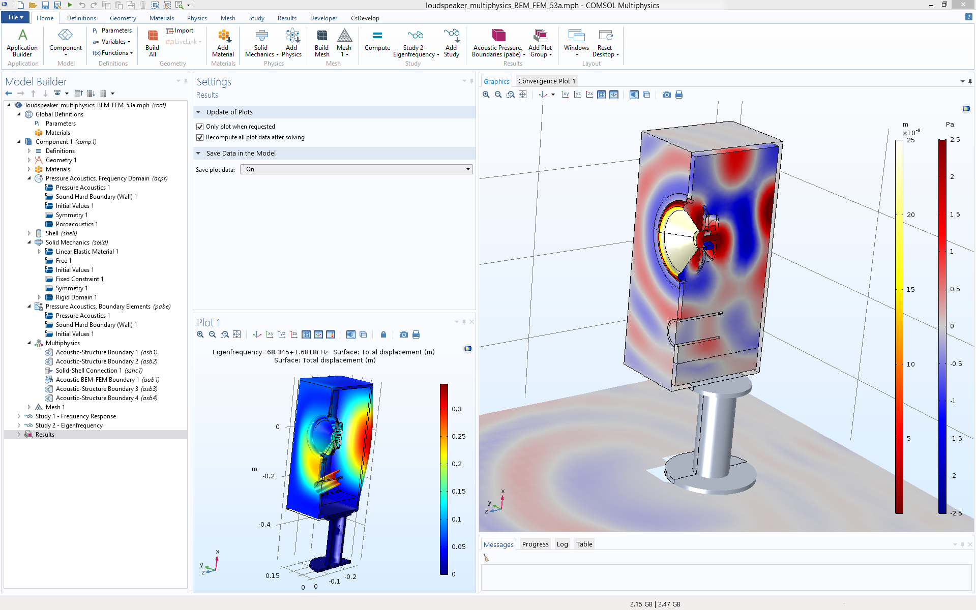
User interface of COMSOL Multiphysics when setting up a multiphysics model of a loudspeaker that includes BEM and FEM acoustics as well as the Solid Mechanics and Shell interfaces. The physics are coupled with the built-in multiphysics couplings. Image from the Vibroacoustic Loudspeaker Simulation: Multiphysics with BEM-FEM tutorial model.
With BEM, you only need to mesh the surfaces next to the modeling domain. This means that there’s less need to create large volumetric meshes (necessary for FEM), making interfaces based on BEM particularly helpful for models that involve radiation and scattering and have detailed CAD geometries. The interface also has built-in conditions to set up an infinite sound hard boundary (wall) or an infinite sound soft boundary. These conditions are very useful when modeling, for example, underwater acoustics, where the ocean surface can be modeled as an infinite sound soft boundary.
Typically, it is advantageous to use interfaces based on BEM for problems with large fluid domains for which a large FEM-based volumetric mesh would otherwise be required (i.e., cases that would run out of memory due to the large 3D mesh). For cases like this one, using BEM can even extend the class of problems that COMSOL Multiphysics can handle. Some examples of these problems include:
- Models with an infinite wall or infinite sound soft boundary that is far (in terms of wavelengths) from the radiating objects
- Models that include the interaction of scattering and radiating objects that are far from each other
- Radiation problems from complex noncompact geometries, where it is difficult to snugly fit a radiation condition or a perfectly matched layer (PML) when using FEM
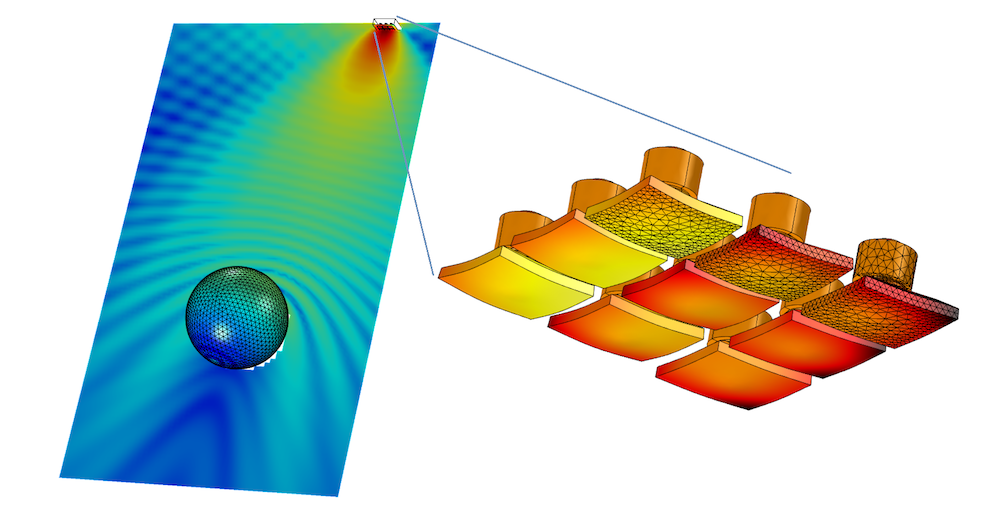
An example of a transducer array located far from a scattering object. This type of problem is very hard or even impossible to solve with a pure FEM-based approach due to the large memory requirement. Using BEM, the model can be solved (moving the sphere further away does not cost more on the computational side). Image from the Tonpilz Transducer Array for Sonar Systems tutorial model.
While BEM is more computationally demanding than FEM for an equal amount of degrees of freedom (DOFs), BEM usually requires far fewer DOFs than FEM to obtain the same accuracy. The fully populated and dense system matrices generated by BEM require different dedicated numerical methods than the ones for FEM. A FEM-based interface, such as the Pressure Acoustics, Frequency Domain interface, is usually faster for solving small- and medium-sized acoustics models than BEM.
According to the user’s guide for the Acoustics Module, the BEM used in the Pressure Acoustics, Boundary Elements interface is based on the direct method with Costabel’s symmetric coupling. To solve the resulting linear system, the adaptive cross approximation (ACA) fast summation method is used. This method uses partial assembly of the matrices where the effect of the matrix vector multiplication is calculated. As for the default iterative solver, it is GMRES. With the built-in multiphysics couplings, it is easy and seamless to set up problems that combine FEM- and BEM-based physics. When solving these coupled models, the default approach is to use hybridization with the ACA for BEM and an appropriate preconditioner for the FEM part of the problem (direct or multigrid).
Getting the Best of Both Worlds: A Hybrid FEM-BEM Approach
As already mentioned, the Pressure Acoustics, Boundary Elements interface seamlessly couples to the finite-element-based interfaces like the Pressure Acoustics, Frequency Domain interface and the Solid Mechanics interface. This coupling makes it possible to easily set up hybrid FEM-BEM models that take advantage of the strengths of each formulation where needed and where they are best applied.
BEM is not meant to replace finite elements in acoustics but should be seen as a complement. The general rule of thumb is to use BEM where large fluid domains would otherwise require a very fine mesh when running a FEM-based model, and to otherwise couple BEM to FEM-based physics where they are best used. Some applications and examples include:
- Modeling transducers and radiation problems with complex geometries
- Model the transducer (piezo or electromagnetic) with FEM and the exterior acoustics with BEM
- Combining interior and exterior problems
- Use FEM in narrow regions and resonant volumes and use BEM for the radiation part
- Remember that acoustics models based on BEM and FEM can easily be coupled using the Acoustic BEM-FEM Boundary multiphysics coupling
Remember that smaller models that fit in memory are typically faster with FEM. Use the traditional approach with a radiation condition or a PML to model open radiation domains.
The Pressure Acoustics, Boundary Elements interface can be used to replace a FEM-based radiation condition or PML and the far-field calculation feature. See, for example, the model example below.
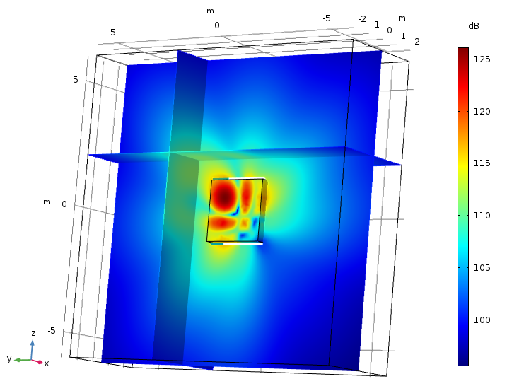
In the Bessel Panel tutorial model, the Pressure Acoustics, Boundary Elements interface is used to model the open space. The BEM interface is effectively replacing a radiation condition (or a PML) and the far-field calculation feature that was previously necessary. This image shows the sound pressure level on the surface of the FEM domain (several point sources are located inside this domain) and in three cut planes, with a given extent, in the exterior BEM region.
Postprocessing BEM Models
When solving a problem with the BEM interface, the resulting solution consists of the dependent variables, equivalently unknown fields, on boundaries. This includes the pressure p and its normal derivative; i.e., the normal flux variable pabe.pbam1.bemflux. Evaluating the solution in a domain is based on an integral kernel evaluation, which is at the heart of BEM.
On boundaries, a dedicated boundary variable is defined. This variable has different definitions on exterior and interior boundaries; it is equal to the dependent variable on exterior boundaries. Up and down pressure-dependent variables are defined on interior boundaries (pabe.p_up and pabe.p_down) because the pressure is discontinuous here; for example, in an Interior Sound Hard Wall boundary. Moreover, on all boundaries, predefined postprocessing variables exist that combine the properties of the boundary variables, when needed, with variables based on the kernel evaluation.
These variables and all other postprocessing variables are found in the Replace Expressions list in the plots, as shown in the image below.
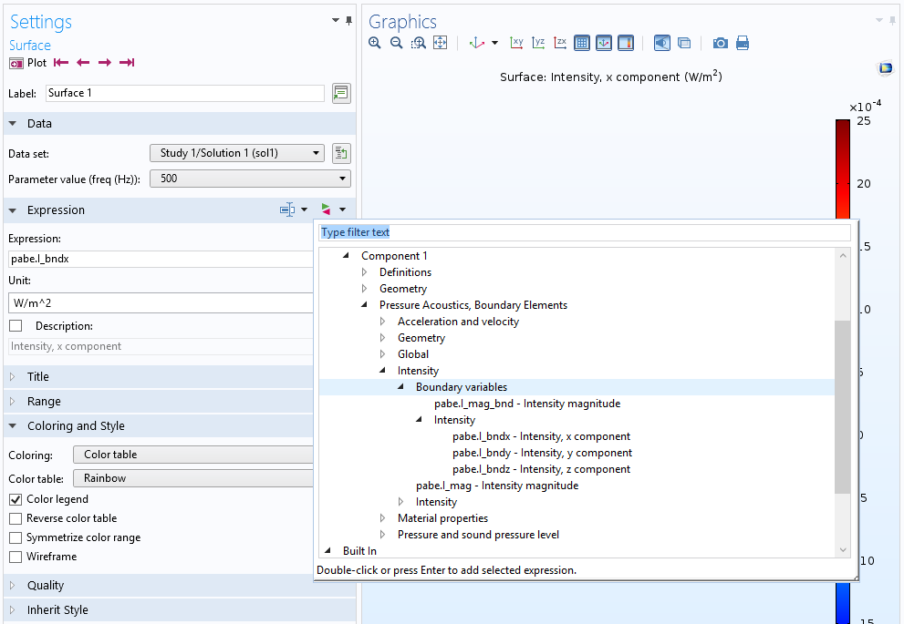
The user interface with a list of some of the predefined postprocessing variables.
When postprocessing the BEM solution within the domains, the pressure field has to be reconstructed using the aforementioned BEM integral kernel evaluation. Dedicated data sets are available for easy visualization of the BEM solution by automating the kernel evaluation on a grid. The paragraphs below discuss data sets that can be used to plot acoustics results.
The Grid 3D and Grid 2D data sets are specially designed for evaluating the solution within domains where there is no mesh. These data sets set up a regular grid of points where the solution is evaluated. The size and bounds of the grid can be modified as well as the resolution (the grid spacing). When visualizing wave problems, it is important to have an adequate spatial resolution. However, the resolution should not be too large, as it will increase the rendering time.
A grid data set can, for example, be selected as the input data set for a slice or a surface plot. A grid data set and a multislice plot are automatically generated and used in the default plots when a BEM model is solved. The grid data set can also be used as input to a cut plane, cut line, or cut point.
Parameterized curves and surfaces can be used directly to evaluate the BEM solution as long as the option Only evaluate globally defined expressions is selected.
The dedicated acoustics plots can be used directly with the BEM variables as input. Examples include the Far Field plot, used for plotting the spatial response (not necessarily in the far field, but as a matter of fact at any distance) and the Directivity plot. For example, the sound pressure level variable pabe.Lp can be used as the expression.
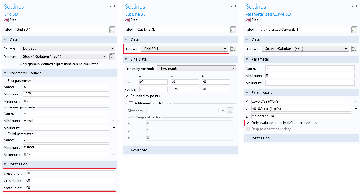
Screenshots of the user interface for some of the different data sets mentioned above. The important settings are highlighted.
The screenshots above are taken from the Loudspeaker Radiation: BEM Acoustics tutorial model. This model solves a radiation problem and has most of the common plots and results visualization set up.
The image below shows the sound pressure level depicted in three slices through the grid on the speaker surface. To illustrate the generality of the postprocessing and visualization tools, the sound pressure level is also shown along a parameterized spiral curve created using a Parametric Curve 3D data set.
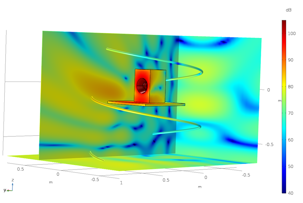
Sound pressure level depicted in different ways in the Loudspeaker Radiation: BEM Acoustics tutorial model.
Two Special Cases of Using BEM
Next, I want to discuss two cases that require special consideration when using BEM.
Case 1: The Half-Space Radiation Problem
Many acoustics applications involve a situation in which a transducer is located in an infinite baffle and is radiating into a half-space. In most cases, this setup is not possible using boundary elements, at least not if the baffle has to be infinite. A noninfinite baffle can be set up using, for example, the Interior Sound Hard Wall boundary condition.
Typically, we would want to use the Infinite Sound Hard Boundary feature. This condition cannot “have a hole in it” like when a loudspeaker driver is sitting in a baffle. Since the BEM formulation is based on the full-space Green’s function, an infinite symmetry plane or an infinite wall condition mean that they are infinite and cannot have an opening in them. Basically, all boundaries that have a selection in the physics interface and are active must be located on the same side of the infinite condition or lie on it. If this is not the case, the results will be unphysical.
My general recommendation for the infinite baffle setups is to use the FEM-based physics interface together with the far-field calculation feature and a PML or radiation condition. For an example, see the Lumped Loudspeaker Driver model. This setup will typically be much faster!
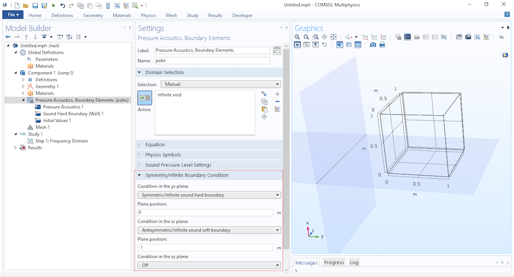
User interface of the Pressure Acoustics, Boundary Elements interface. The infinite conditions are found at the top physics level (highlighted here). Once a condition is selected, the resulting plane is depicted in the Graphics window.
Case 2: Interior Problems
Interior problems — especially problems with sharp resonances where no or little loss is present — can be challenging to solve with BEM. This is not because of the method itself but because an iterative solver is used to efficiently solve the underlying matrix system. The same problem is also found for a FEM-based model that uses an iterative solver.
Near a sharp resonance, any small change results in variations in the pressure that are hard to capture to ensure convergence. If possible, use FEM in these situations together with a direct solver or make sure to add realistic boundary conditions with losses, such as an impedance condition.
Concluding Remarks on the Boundary Element Method
BEM is a very useful complement to FEM in the COMSOL Multiphysics environment. Many engineers in the acoustics modeling community have been looking forward to the addition of this functionality. We hope that you will enjoy this latest addition to the Acoustics Module.
Next Steps
See what’s possible with the specialized acoustics modeling features available in the Acoustics Module add-on product by clicking the button below.
Try it yourself: Download one of the tutorial models featured in this blog post. From the Application Gallery, you can log into your COMSOL Access account and download the MPH file.




Comments (12)
Pu Zhang
March 20, 2018It’s interesting to see BEM being incorporate into COMSOL. Would such extension be available for more modules, e.g., RF module?
Mads Herring Jensen
April 4, 2018 COMSOL EmployeeDear Pu,
BEM is already available in the stationary electromagnetic cases (at low frequencies) when solving electrostatic and magnetostatic problems (in the AC/DC module). BEM for RF will eventually be added in the future but we do not have clear plans yet.
Best regards
Mads
Pei-Tai Chen
July 6, 2018Dear Sir:
Thanks for you introducing the BEM capability. I like to know the way of structural equation FEM coupled to acoustic BEM, specifically, the equation of FEM is coupled to BEM equation and the two equations solved simultaneously. The other way coupling sometime is simplying to solve equation first, then, importing solved displacement into BEM equation. For example, a submerged spherical thin shell structure in the water subjected an external force, can the coupling of FEM and BEM be solved this problem by exact direct coupling ?
Mads Herring Jensen
July 9, 2018 COMSOL EmployeeDear Pei-Tai
We solve the equations fully coupled with couplings in both directions. This is true when coupling BEM to both acoustics FEM and structural FEM. The problem is solved with an iterative solver that uses a hybrid preconditioner to handle the FEM part of the matrix and the BEM part separately. So your problem with a thin submersed spherical shell will be modeled correctly!
Best regards
Mads
Kiumars Aryana
August 5, 2018Dear Mads,
Is it possible to use Pressure Acoustics Boundary Element for a time domain study? I tried to do it but I get this error: “Undefined variable. – Variable: freq” Although I defined sinusoidal pressure of: 10e6*sin(2*pi*8[GHz]*t[s]) and I do not have a “freq” variable. I guess it is a variable comsol only gets from the frequency domain!
Thanks
Kiumars
Mads Herring Jensen
August 6, 2018 COMSOL EmployeeDear Kiumars
The boundary element method only works for the frequency domain. When you add the physics from the wizard or use the dynamic help (F1) this is stated clearly. I know that certain academic codes also use BEM in the time domain but I do not think it is very efficient. For large transient models I recommend that you use the Pressure Acoustics, Time Explicit interface that is based on the discontinuous Galerkin (DG) method.
Best regards
Mads
Kossivi GOKPI
March 29, 2021Dear sir,
I read the coupling FEM with BEM.
I’m interrested in using FEM in narrow regions and use BEM for the radiation part to compute the pressure at very far field away from the narrow region.
I would like to know how the FEM computed at the boundary served as boundary conditions to the BEM part ?
Then does it means that the BEM to compute the very far field pressure is only a post-processing trough the BEM equation?
Best regards,
Kossivi
Mads Herring Jensen
March 29, 2021 COMSOL EmployeeDear Kossivi
The BEM implementation of the Helmholtz equation is solve coupled with FEM i order to model the open infinite domain. So this will give you a combined ideal radiation condition as well as easy postprocessing of the near to far-field.
Best regards
Mads
Gyani Shankar Sharma
July 6, 2021Hi Mads,
Can the BEM module be coupled with the fluid-structure interaction modules? In other words, can COMSOL model fluid-structure-acoustic interaction problems?
Best regards,
Gyani
Mads Herring Jensen
July 6, 2021 COMSOL EmployeeHi Gyani
Yes, this is also explained in the blog post, I think. The BEM based acoustics can be coupled to vibrating structures with our built-in Multiphysics couplings. So all this works out of the box. This is of course only in the frequency domain.
What do you mean by fluid-structure-acoustic problems? If you solve a fluid flow problem that couples CFD to a structure you can make an FFT of the time domain response and use that as input to an acoustic simulation.
Best regards
Mads
NAHEED TABASSUM
August 17, 2021Can I use BEM for circular of Curvature Tonpilz Transducer Arrays? Can you kindly explain about Submerged and Excluded Boundary Condition in BEM Method.
Mads Herring Jensen
September 8, 2021 COMSOL EmployeeDear Naheed
You can use the BEM interface for any shape of the transducers. The Excluded boundary us used when modeling a half-space problem using the symmetry/infinite plane feature. You need to exclude all boundaries on the “other side” of the plane.
Best regards
Mads