

MEMS gyroscopes help machines and devices orient themselves. In the automotive industry, these gyroscopes are used in advanced safety systems such as electronic stability control, ride stabilization, and rollover detection systems. Inaccuracies in these systems can have serious consequences, making the design and manufacturing of reliable and consistent gyroscopes crucial.
In this blog post, we’ll look at three comb-drive tuning fork rate gyroscope models, highlighting the benefits of equation-based modeling, how modeling can capture the impact of manufacturing variations, and the use of a mixed element formulation in design.
Model Overview
The geometry used for the gyroscope models shown here, as well as the equation-based modeling approach used for the first model, was provided by Veryst Engineering, LLC. The models feature drive and sense modes coupled through Coriolis forces. The driving and sensing mechanisms (which use electrostatic actuation and capacitive sensing, respectively) provide enhanced sensitivity levels compared to some other MEMS gyroscope designs. The design also includes two proof masses that are supported by springs anchored to a substrate (which is not explicitly modeled). The masses are driven to move in the opposite directions with equal amplitudes.
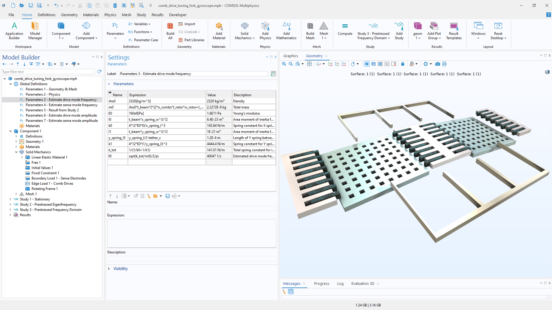 The COMSOL Multiphysics® user interface showing the model parameters.
Equation-Based Modeling in Gyroscope Design
The first model we’ll look at is solved to find the stationary displacement, resonant frequencies, and its response to rotation. The model provides insight into the operation of this type of MEMS gyroscope and how to best model similar devices. In the model, the comb drives are DC-biased at 60 V and AC-excited at 3 V, while the sense electrodes are DC-biased at 5 V. While a predefined Electromechanics multiphysics coupling is available in the MEMS Module, an add-on to the COMSOL Multiphysics® software, this model alternatively can be used for computing electrostatic forces in a single-physics problem.

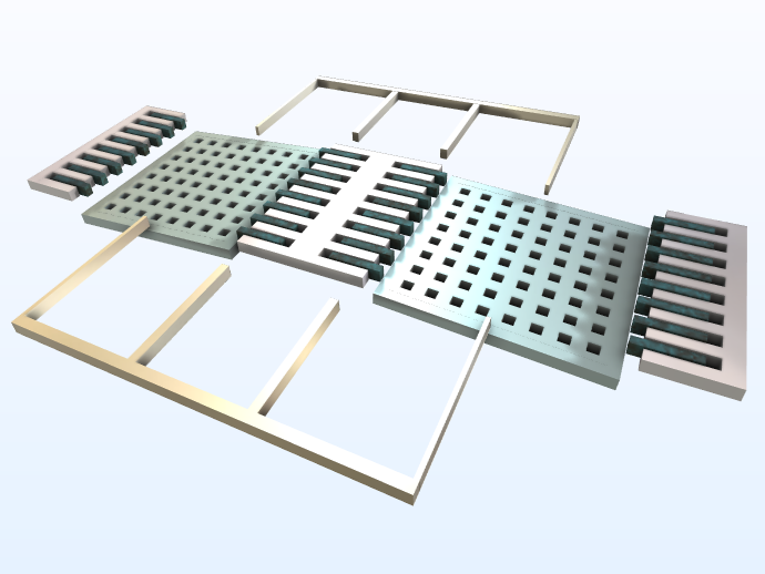
The gyroscope model with (left) and without (right) deformation.
This approach uses equations that serve as approximations to the coupled electrostatics and solid mechanics and improves the solution speed. To further save time and file size, the mesh is relatively coarse. The numerical results of this model can be compared to well-known analytical estimations of the drive-mode and sense-mode frequencies.
| Drive Mode | Sense Mode | |
|---|---|---|
| Numerical | 38 kHz | 41 kHz |
| Analytic | 40 kHz | 45 kHz |
Modeling Variations in Manufactured Parts
Complex designs may lead to manufacturing variations that result in variation in the devices’ performances. For this reason, many engineers take a design-for-manufacturing approach, which is a process that focuses on altering aspects of a design that would be difficult for manufacturers to replicate consistently.
COMSOL Multiphysics® can be used to estimate the effects that manufacturing variations have on a design. The Deformed Geometry feature enables users to implement multiple device shape changes that result from fabrication imperfections using the same mesh. This eliminates the possibility of errors that can occur when using different meshes for different geometries.
In this model example, manufacturing variations have been added to the device, including:
- The effect of over-etching resulting in critical dimension (CD) variation (50 nm over-etching)
- Device layer thickness variations (100 nm thickness change)
- A side-wall tilt (.5 degree) parameterized by the steepest angle to the vertical (theta) and an in-plane angle (phi)
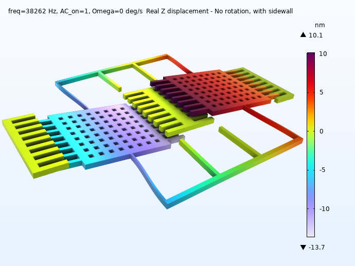
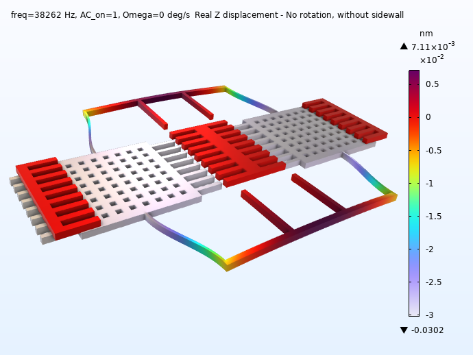
Displacement of the device during operation without rotation, with (left) and without (right) side-wall tilt.
The solved model shows that the mode spacing (difference in frequency between adjacent modes) is strongly affected by the CD control and the 50 nm over-etching causing large changes in the spacing of the modes.
| Frequencies | Drive Mode | Sense Mode |
|---|---|---|
| Standard mode frequency (kHz) | 38.262 |
|
| Frequency shift due to 50 nm over-etching (kHz) | -1.272 |
|
| Frequency shift due to 100 nm thickness change (kHz) | 0.001 |
|
| Frequency shift due to .5-degree side wall (kHz) | -0.003 |
|
As seen by the results, the drive mode is relatively unaffected by the thickness variations and side wall, whereas the sense mode is significantly affected by the thickness since it involves out-of-plane motion.
These simulation results can inform designers if a fabrication process could yield devices with desired performance or if the design should be altered. Having this insight before production saves time and resources.
Micromachined Gyroscope with Mixed Formulation
While the two previous models include only solid mechanics, the third model includes solid mechanics and electromechanics and fully accounts for the interaction between them. This is true multiphysics modeling, highlighting how a multiphysics problem would typically be handled in COMSOL®.
The model does not need user-defined analytical equations, so it is much easier to set up. To illustrate this point, the original model required 40 selections relating to the application of user-defined equations, whereas the multiphysics model uses only 14 selections. The results are predictably different than from the previous two models, as the multiphysics approach result in a stronger force between the comb-drive stators and rotors and, consequently, slightly lower resonance frequencies. The model also uses the mixed element formulation for electrostatics introduced in COMSOL Multiphysics® version 6.3. This formulation solves for both the electric potential (V) and the electric displacement field (D), which results in more accurate electrostatic force calculations, especially for complicated structures with many sharp edges and corners. For this reason, the formulation is well suited for modeling gyroscopes and accelerometers with comb-drive actuators.
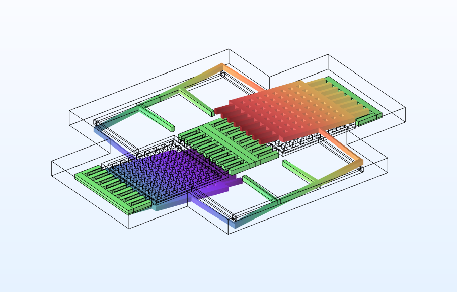 The mode shapes of the out-of-plane sense mode.
| Drive Mode | Sense Mode | |
|---|---|---|
| Multiphysics, mixed formulation | 36 kHz | 40 kHz |
| Solid mechanics only (first model) | 38 kHz | 41 kHz |
Try the Models for Yourself
With COMSOL Multiphysics®, you can quantify the impact that manufacturing variations have on designs and use an equation-based approach to make your modeling more efficient. Additionally, multiphysics couplings can be used to improve design accuracy.
To model the examples presented here, check out the Application Gallery entries, which include step-by-step instructions and MPH files for the models:
- First example: A Micromachined Comb-Drive Tuning Fork Rate Gyroscope
- Second example: Manufacturing Variation Effects in a Micromachined Comb-Drive Tuning Fork Rate Gyroscope
- Third example: Micromachined Gyroscope with Mixed Formulation

Comments (0)