Introduction to Magnetohydrodynamic Flow Modeling
In the first part of this course, you'll get an introduction to the topic of magnetohydrodynamics. We will define magnetohydrodynamic flow, discuss some common applications of it, and provide an overview of the modeling process for simulating magnetohydrodynamic flow in the COMSOL Multiphysics® software.
What is Magnetohydrodynamics?
The name magnetohydrodynamics stems from magneto, which relates to magnetic fields, and hydrodynamics, which relates to the motion of fluid. As such, magnetohydrodynamics (MHD) is the study of the flow of a conductive liquid inside a magnetic field. The magnetohydrodynamic effect can be summarized as:
The motion
of a fluid of conductivity
in a magnetic field
induces an electromotive force (EMF) in the fluid, characterized by the appearance of a current density
in the fluid.
may also be known as the Lorentz term current.
The current flowing in the magnetic field causes the Lorentz force
to act on the fluid.
This forms a nonlinear system: The current density also induces a magnetic field, which then contributes to defining
, creating a dependency for
on itself. Similarly,
is dependent on the flow profile
, which will be modified by the Lorentz force acting on the fluid, and the Lorentz force is dependent on
.
The resulting flow in these systems can then differ significantly compared to the flow of the fluid in them when there is no magnetic field present.
Below, three flow profiles for liquid flowing in a square duct are presented. The first example is the standard laminar flow profile. The other two flow profiles are two of the possible profiles that can be achieved by adding a uniform magnetic field to the system; which profile is achieved is dependent on the electrical conductivity of the walls of the duct. T he central profile is achieved by having all of the walls made of perfect insulators. This is known in the literature as Shercliff's case. The example on the right is known as Hunt's case. It is achieved by having w alls parallel to the magnetic field (side walls) made of perfect insulators, and w alls normal to the magnetic field (Hartmann walls) made of perfect conductors.

Flow profiles in a square duct: laminar flow (left), MHD flow under the conditions for Shercliff's case (center), and MHD flow under the conditions for Hunt's case (right).
It is seen that the Lorentz force acts as a damping force in the core of the flow, resulting in a more uniform flow velocity here. Additionally, the thickness of the boundary layers, known as Hartmann layers, decreases. This process can introduce complex behaviors, such as areas of significantly increased flow, known as jets. Furthermore, under the right wall conditions and with a sufficiently strong magnetic field, it is even possible for the direction of the fluid flow to reverse in parts of the cross section.
Dimensionless Quantities — the Hartmann and Magnetic Reynolds Numbers
In standard fluid flow modeling, there are a number of key dimensionless quantities that are used to understand the flow regime and the ratios of different forces in the fluid, the most important being the Reynolds number, which identifies whether the flow is expected to be laminar or turbulent.
Magnetohydrodynamics has its own set of dimensionless quantities that are used to qualify the flow regime and ratios of forces in the model. The most important of these is the Hartmann number, , which gives the ratio of the strength of the electromagnetic forces to the viscous forces. It is defined as
where is the magnitude of the magnetic flux density,
is the characteristic length of the system,
is the conductivity of the fluid, and
is its dynamic viscosity. The higher the Hartmann number, the larger the effect the Lorentz force will have on the fluid. For large Hartmann numbers, the system becomes highly nonlinear, and specific solver techniques have to be applied in order to solve the model.
There is a second dimensionless quantity that can be tracked in the model, the magnetic Reynolds number, which can be used to estimate the impact that the electromotive force has on the system by estimating the ratio between the magnetic field induced from it and the magnetic diffusion
where is the permeability of the fluid. The magnetic Reynolds number is used to identify cases where the contribution of the electromotive force to the magnetic field can be neglected and quasistatic modeling is performed. This occurs when
.
Applications of Magnetohydrodynamics

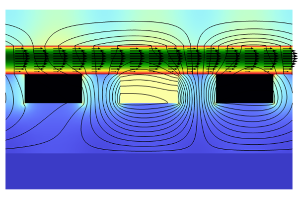
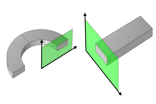
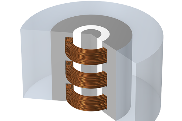
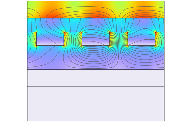
Three common applications of MHD: fluid pumping (left), arc discharge (center), and an approximation of equilibrium plasmas modeling (right).
The phenomena involved in the magnetohydrodynamic effect can be utilized in a number of diverse applications. While these applications can be very different, the underlying processes are often interconnected, and studying each of them can lead to a broader understanding and utilization of MHD simulation.
The first application is generating fluid motion. By placing coils around fluid containers and pipes and driving them with alternating current (AC), currents are induced in the fluid along with a magnetic field, which applies a Lorentz force to the fluid. This technique can create a pumping effect in pipes or stir fluid in a container, achieving motion without the need for moving parts that may degrade and wear out quickly. This method's efficiency and reliability make it highly advantageous in various industrial processes.
Transitioning from fluid motion to measurement, MHD also plays a crucial role in monitoring fluid flow. For instance, placing electromagnets around a pipe in which fluid is flowing will generate a potential difference across the pipe that can be measured to determine the flow rate. This nonintrusive method avoids introducing components inside the pipe that would impede the flow, allowing for accurate flow measurements with minimal impact on the fluid's movement. Such precise measurement techniques are essential in fields that require careful flow monitoring, such as chemical processing and water treatment.
Expanding on the theme of measurement, MHD systems can also be adapted to create precise rotational velocity sensors for navigation systems. A spun toroid filled with fluid will cause the fluid inside to also rotate. When this is then placed in a background magnetic field, an induced potential difference between the walls can then be measured. This effect can create very sensitive sensors.
Another significant application of MHD is found in nuclear fusion reactor designs. These reactors often use magnetic confinement methods for the fusion plasma. In these designs, the liquid metal forming the blanket travels within this magnetic field, making the system inherently magnetohydrodynamic. Understanding and optimizing these systems is critical for the advancement of nuclear fusion technology that promises a sustainable energy future.
Theoretical studies of MHD systems also provide foundational insights, often focusing on the flow of liquid metals in pipes, ducts, and channels within uniform background fields. For these systems, exact or asymptotic analytic solutions can often be calculated, allowing MHD modeling techniques to be benchmarked. These studies are not only academically valuable but also practical for understanding liquid metal transport within magnetic fields, informing the design of efficient industrial systems.
Lastly, equilibrium plasmas — plasmas in thermal equilibrium where the gas and species temperatures match — can be approximated as conductive fluids with temperature-dependent electrical conductivity, density, and viscosity. With heat sources to represent the chemical reactions in the plasma, the nonisothermal MHD equations can then be used to model the behavior of these plasmas. Examples of equilibrium plasma discharges include inductively coupled plasma torches, electric arc discharges at atmospheric pressure, and high-pressure, high-temperature thermal plasmas.
Introduction to Modeling Magnetohydrodynamics in COMSOL®
The methodology for modeling MHD systems in COMSOL® is the same as for any multiphysics phenomenon. That is, one physics interface is included for each area of physics in the model, and then a multiphysics coupling is used to add the couplings between these interfaces.
For magnetohydrodynamics it is necessary to use two physics interfaces: one for the electromagnetic physics and one for the fluid flow.
For the electromagnetics interface, one of the Magnetic Fields; Magnetic and Electric Fields; Magnetic Field Formulation; and Rotating Machinery, Magnetic interfaces can be used. Which of these four interfaces should be chosen is dependent on the dimension of the component used in the model and the currents within it. How to make this choice is discussed in Part 2 of this course.
The fluid flow interface will generally be the Laminar Flow interface. This is also discussed in Part 2 of this course.
The two interfaces are then coupled together using the Magnetohydrodynamics coupling in the AC/DC Module that applies electromotive force as a current in the electromagnetic interface and the Lorentz force as a volume force in the Laminar Flow interface.
 A screenshot of the Magnetohydrodynamics multiphysics coupling showing the interfaces coupled.
A simple magnetohydrodynamics model of a liquid metal pump, showing the Magnetic Fields and Laminar Flow interfaces being used with the Magnetohydrodynamics coupling.
The interfaces then need to be set up with the appropriate domain and boundary conditions, and the model needs to be meshed and configured in order to solve efficiently. The rest of this course will discuss how to do this.
Submit feedback about this page or contact support here.


