Geomechanics Module

Expand Structural Analyses for Geotechnical Applications

Analyzing tunnels, excavations, slope stability, and retaining structures requires nonlinear material models specialized for geotechnical applications. The Geomechanics Module, an add-on to the Structural Mechanics Module, includes built-in material models for modeling deformation, plasticity, creep, and failure in soils, concrete, and rock. The module also includes standard nonlinear material models for describing metal plasticity through the von Mises and Tresca criteria. These material models enhance the safety and failure evaluation features that are included in the Structural Mechanics Module.

Contact COMSOL
A rectangular concrete beam model showing the stress with rainbow reinforcement bars located on the top and bottom.

Geomechanics Materials for Multiphysics Modeling

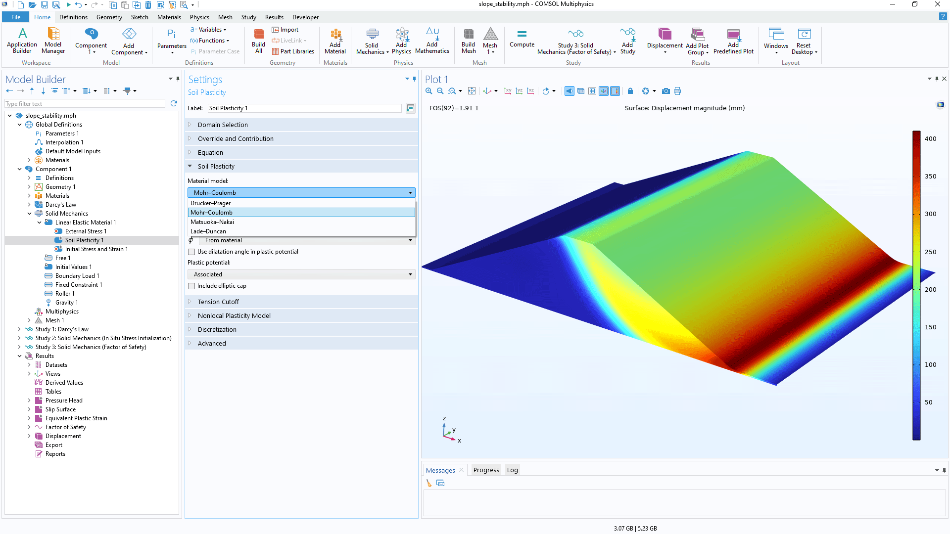
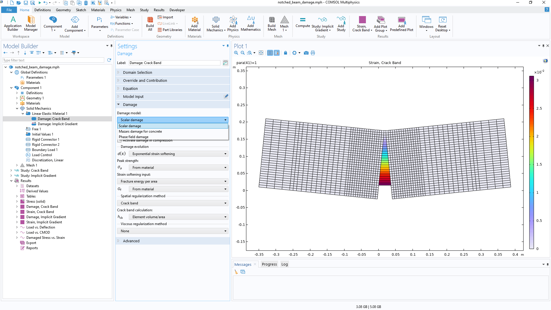
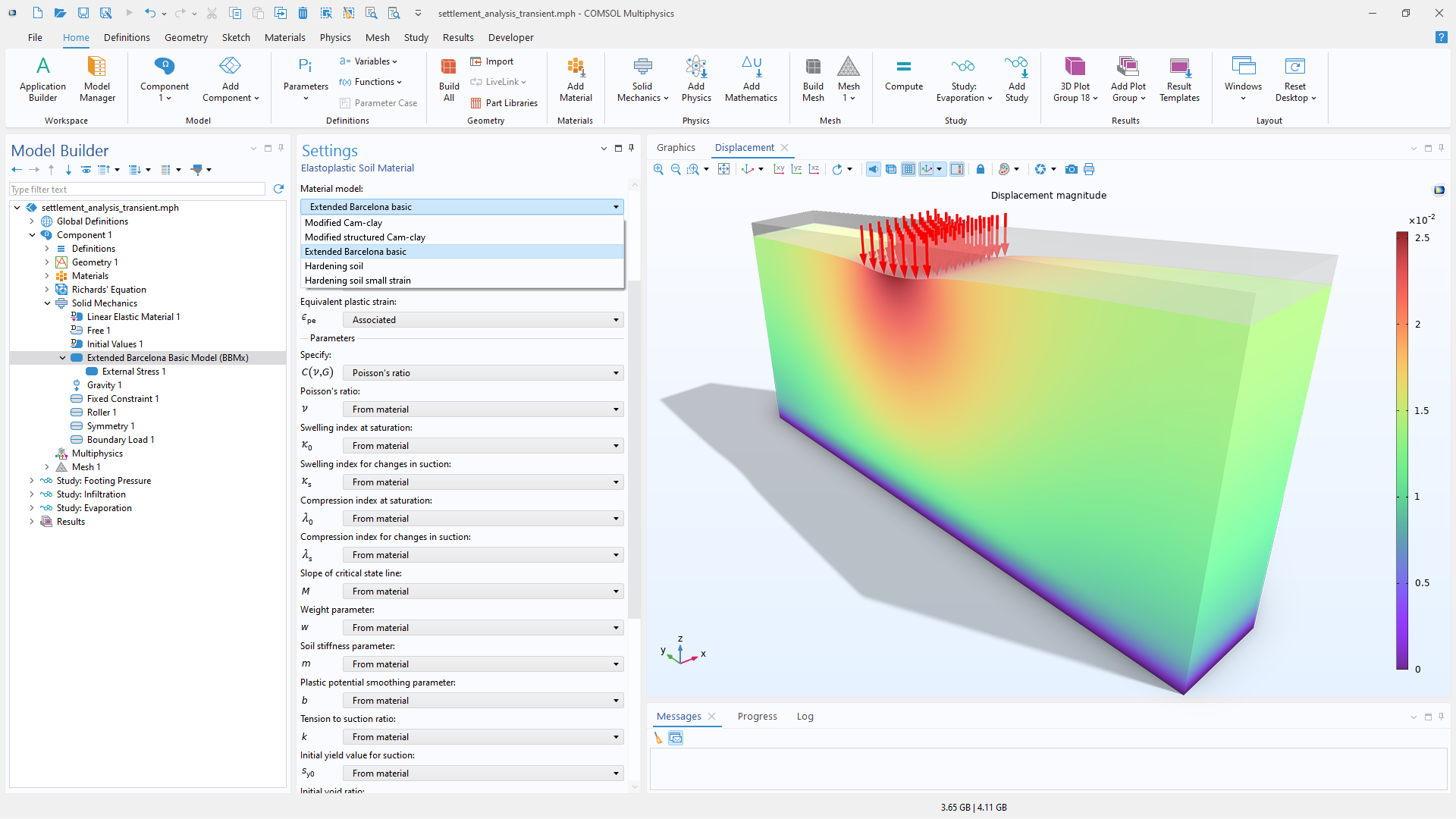
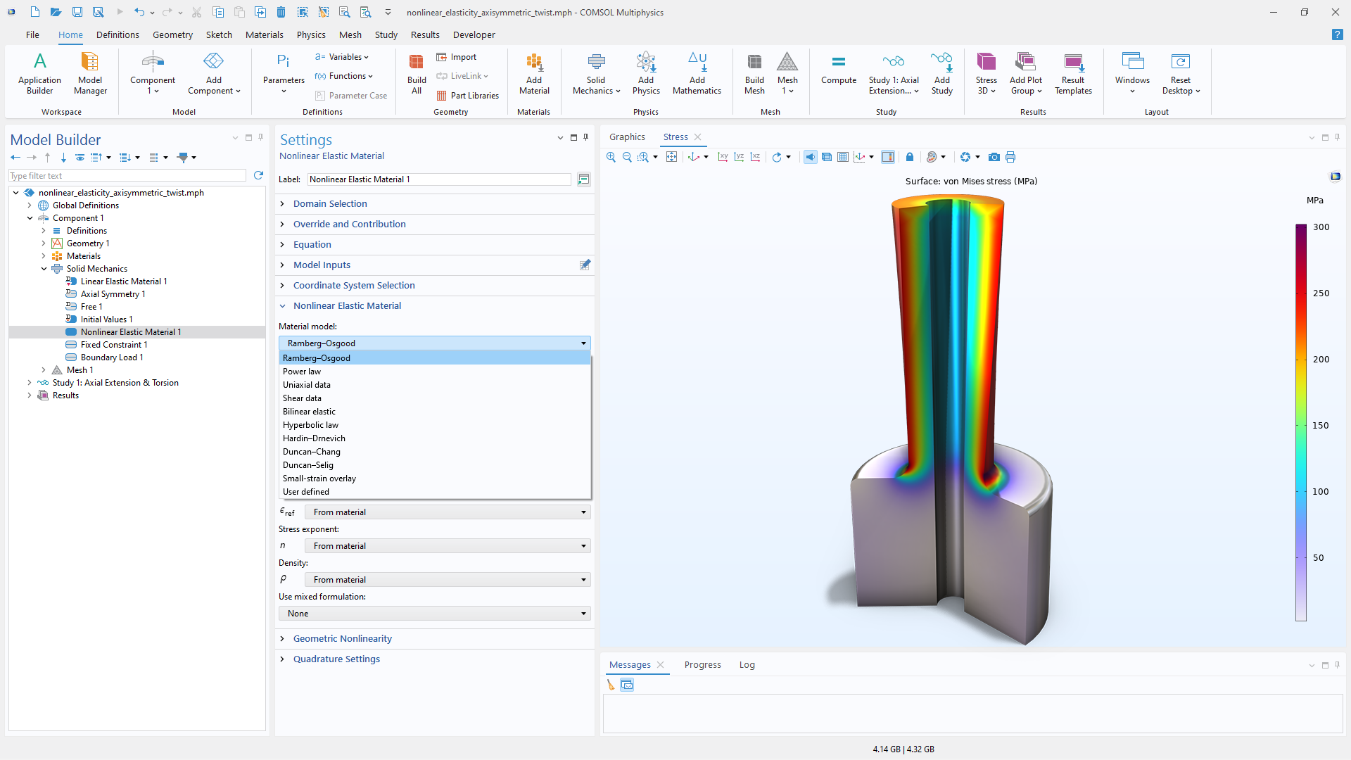
The functionality for modeling geomechanics materials augments all of the structural analyses available within the Structural Mechanics Module. To accurately account for real-world effects and behavior in geotechnical analyses, multiphysics effects can be included by combining the features and functionality in the Geomechanics Module with other modules in the COMSOL product suite. For instance, it is possible to model porous media flow, poroelasticity, solute transport, and heat transfer with the Subsurface Flow Module.

Material Models in the Geomechanics Module

The numerous material models available are listed below, with screenshots of their implementation in the software.

A close-up view of the Soil Plasticity settings and a slope stability model in the Graphics window.

Soil Plasticity

The Geomechanics Module can be used to define the properties for modeling materials exhibiting soil plasticity. These material models can be used together with linear and nonlinear elastic materials and can be combined with damping, thermal expansion, fibers, and other features. The following soil models are available:

  • Mohr–Coulomb
  • Drucker–Prager
  • Matsuoka–Nakai
  • Lade–Duncan
  • Cap
    • Elliptic
    • Planar
    • Hardening
  • Cutoff
    • Mean stress
    • Rankine
  • Nonlocal plasticity
    • Implicit gradient
A close-up view of the Concrete settings and a beam model in the Graphics window.

Concrete and Rock

The Geomechanics Module includes functionality for defining the properties of materials with failure criteria representative of concrete and rock, including failure due to tensile stress. These material models can be used together with the Linear Elastic Material and Nonlinear Elastic Material features. The following concrete and rock material models are available:

Concrete

  • Ottosen
  • Bresler–Pister
  • Willam–Warnke
  • Coupled damage–plasticity
  • Mazars damage
  • Tension cutoff

Rock

  • Original Hoek–Brown
  • Generalized Hoek–Brown
  • Tension cutoff
A close-up view of the Damage settings and a notched beam model in the Graphics window

Damage

The deformation of quasibrittle materials, such as concrete or ceramics, under mechanical loads is characterized by an initial elastic deformation. If a critical level of stress or strain is exceeded, a nonlinear fracture phase will follow the elastic phase. As this critical value is reached, cracks grow and spread until the material fractures. The occurrence and growth of the cracks play an important role in the failure of brittle materials, and there are a number of theories to describe such behavior. The following damage models are available:

  • Scalar damage
  • Mazars damage for concrete
  • Equivalent strain criterion
    • Rankine
    • Smooth Rankine
    • Norm of elastic strain tensor
    • User defined
  • Phase field damage
  • Regularization
    • Crack band
    • Implicit gradient
    • Viscous regularization
A close-up view of the Elastoplastic Soil Material settings and a 1D plot in the Graphics window.

Elastoplastic Soil

The Elastoplastic Soil Material feature is used to model stress–strain relationships that are nonlinear even at infinitesimal strains. The following soil material models are available:

  • Modified Cam–Clay
  • Modified structured Cam–Clay
  • Extended Barcelona basic
  • Hardening soil
  • Hardening soil small strain
  • Large-strain plasticity
  • Nonlocal plasticity
    • Implicit gradient
A close-up view of the Model Builder with the Elastoplastic material model node selected and a bar necking model in the Graphics window.

Elastoplastic Ductile Materials

In addition to elastoplastic material models for soil, the Geomechanics Module includes the following material models and plasticity options for ductile materials, such as metals:

  • von Mises
  • Tresca
  • User-defined plasticity
  • Large-strain plasticity
  • Isotropic and kinematic hardening
  • Nonlocal plasticity
    • Implicit gradient

Additional elastoplastic material models are available in the Nonlinear Structural Materials Module.

A close-up view of the Nonlinear Elastic Material settings and a 1D plot.

Nonlinear Elasticity

As opposed to hyperelastic materials, where the stress–strain relationship becomes significantly nonlinear at moderate to large strains, nonlinear elastic materials present nonlinear stress–strain relationships even at infinitesimal strains. The following nonlinear elasticity models are available:

  • Ramberg–Osgood
  • Hyperbolic law
  • Hardin–Drnevich
  • Duncan–Chang
  • Duncan–Selig
  • Small-strain overlay
  • User defined

Additional material models are available with the Nonlinear Structural Materials Module.

A close-up view of the Creep settings and a 3D hollow sphere model in the Graphics window.

Creep

Creep is an inelastic time-dependent deformation that occurs when a material is subjected to stress (typically much less than the yield stress) at sufficiently high temperatures. The Geomechanics Module includes support for user-defined creep as well as inputting user-defined inelastic strain rate expressions.

Additional material models are available with the Nonlinear Structural Materials Module.

Every business and every simulation need is different.

In order to fully evaluate whether or not the COMSOL Multiphysics® software will meet your requirements, you need to contact us. By talking to one of our sales representatives, you will get personalized recommendations and fully documented examples to help you get the most out of your evaluation and guide you to choose the best license option to suit your needs.

Just click on the "Contact COMSOL" button, fill in your contact details and any specific comments or questions, and submit. You will receive a response from a sales representative within one business day.

Next Step

Request a Software Demonstration